Samsung DVD-HR720 User Manual (user Manual) (ver.1.0) (English) - Page 15
Rear Panel, ANT IN/ANT OUT TO TV
 |
View all Samsung DVD-HR720 manuals
Add to My Manuals
Save this manual to your list of manuals |
Page 15 highlights
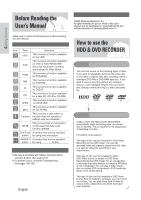
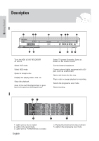
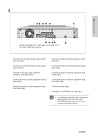
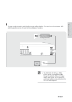
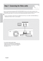
Rear Panel Getting Started Fan Ensure a minimum of 4" clear space on all sides of the fan when installing the product. 1. DIGITAL AUDIO OUT(OPTICAL) Connects to an amplifier having a digital optical audio input jack. 2. DIGITAL AUDIO OUT(COAXIAL) Connects to an amplifier having a digital coaxial audio input jack. 3. AV AUDIO OUT Connects to the audio input of external equipment using audio cables. 4. AV VIDEO OUT(good video quality) Connects the input of external equipment using a Video cable. 5. AV S-VIDEO OUT(better video quality) Connects the input of external equipment using an S-Video cable. 6. COMPONENT VIDEO OUT(best video quality) Connects to equipment having Component video input jacks. 7. AV 1 AUDIO IN Connects the output of external equipment using audio cables. 8. AV 1 VIDEO IN Connects the output of external equipment using a video cable. 9. AV 1 S- VIDEO IN Connects the output of external equipment using an S-Video cable. 10. ANT IN/ANT OUT (TO TV) Connects antenna cables. 11. G-LINK Connection of the IR Blaster for a cable box. I The Antenna connection does not pass the output signal of the DVD. To watch NOTE DVD/HDD playback your TV, you must connect audio/video cables. English - 15
-
 1
1 -
2
-
3
-
4
-
5
-
6
-
7
-
8
-
9
-
 10
10 -
 11
11 -
 12
12 -
 13
13 -
 14
14 -
 15
15 -
 16
16 -
 17
17 -
 18
18 -
 19
19 -
 20
20 -
21
-
22
-
23
-
24
-
25
-
26
-
27
-
28
-
29
-
30
-
31
-
32
-
33
-
34
-
35
-
36
-
37
-
38
-
39
-
40
-
41
-
42
-
43
-
44
-
45
-
46
-
47
-
48
-
49
-
50
-
51
-
52
-
53
-
54
-
55
-
56
-
57
-
58
-
59
-
60
-
61
-
62
-
63
-
64
-
65
-
66
-
67
-
68
-
69
-
70
-
71
-
72
-
73
-
74
-
75
-
76
-
77
-
78
-
79
-
80
-
81
-
82
-
83
-
84
-
85
-
86
-
87
-
88
-
89
-
90
-
91
-
92
-
93
-
94
-
95
-
96
-
97
-
98
-
99
-
100
-
101
-
102
-
103
-
104
-
105
-
106
-
107
-
108
-
109
-
110
-
111
-
112
-
113
-
114
-
115
-
116
-
117
-
118
-
119
-
120
-
121
-
122
-
123
-
124
-
125
-
126
-
127
-
128
-
129
-
130
-
131
-
132
-
133
-
134
-
135
-
136
-
137
-
138
-
139
-
140
-
141
-
142
-
143
-
144
-
145
-
146
-
147
-
148
-
149
-
150
-
151
-
152
-
153
-
154
-
155
-
156
-
157
-
158
-
159
-
160
-
161
-
162
-
163
-
164
-
165
-
166
-
167
-
168
 |
 |
