Sharp PN-V701 PN-V701 Operation Manual - Page 14
Connecting Peripheral Equipment, Mounting the control kit optional on the, monitor
 |
View all Sharp PN-V701 manuals
Add to My Manuals
Save this manual to your list of manuals |
Page 14 highlights
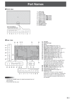
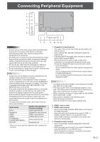
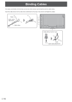
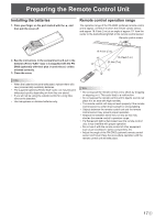
Connecting Peripheral Equipment n Mounting the control kit (optional) on the monitor If performing operation of the monitor with the remote control unit, the PN-ZR02 control kit (optional) is required. • Can perform operation of an arbitrary monitor or all monitors with the remote control unit of the first monitor. • Can perform operation of up to 25 monitors. • Connect the monitors together in a daisy chain with RS-232 cable. 4. Insert the remote control sensor box connection cable into the control kit terminal. Remote control sensor box Connection cable Attach the remote control sensor box as shown in the following illustration. For the monitor in landscape orientation For the monitor in portrait orientation Control kit terminal Caution • When attaching the remote control sensor box, turn the main power switch OFF. • Except for the remote control sensor box connection cable, do not insert any other cable into the control kit terminal. Also, do not connect any connection cables that have been extended with commercially available cables. Caution • When attaching the remote control sensor box, turn the main power switch OFF. 1. Peel off the sticker ( ) that has been affixed to the monitor's remote control sensor box mounting hole. 2. Secure the mounting bracket by inserting the mounting screw into the monitor's remote control sensor box mounting hole. 3. Adjust the angle of the remote control sensor box, and secure it with the fixing screw, so that it may accurately receive signals from the remote control unit. Fixing screw Mounting screw Mounting bracket Angle adjustment Remote control sensor box Remote control sensor box mounting hole TIPS • To conceal the remote control sensor box mounting hole, affix an included sticker over the hole. E 14
-
 1
1 -
2
-
3
-
4
-
5
-
6
-
7
-
8
-
 9
9 -
 10
10 -
 11
11 -
 12
12 -
 13
13 -
 14
14 -
 15
15 -
 16
16 -
 17
17 -
 18
18 -
 19
19 -
20
-
21
-
22
-
23
-
24
-
25
-
26
-
27
-
28
-
29
-
30
-
31
-
32
-
33
-
34
-
35
-
36
-
37
-
38
-
39
-
40
-
41
-
42
-
43
-
44
-
45
-
46
-
47
-
48
-
49
-
50
-
51
-
52
-
53
-
54
-
55
-
56
-
57
-
58
-
59
-
60
-
61
-
62
-
63
-
64
-
65
-
66
-
67
-
68
-
69
-
70
 |
 |
