Sharp PN-V701 PN-V701 Operation Manual - Page 9
Part Names
 |
View all Sharp PN-V701 manuals
Add to My Manuals
Save this manual to your list of manuals |
Page 9 highlights
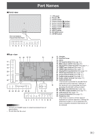
nFront view 1 The rear buttons if seen from the front Part Names 1. LCD panel 2. Power LED 3. Power button 4. Cursor control ( ) button 5. Cursor control ( ) button 6. Cursor control ( ) button 7. Cursor control ( ) button 8. MENU button 9. INPUT button 10. RETURN button 11. ENTER button 11 10 9 8 7 6 5 4 3 2 nRear view 12 30 13 14 17 18 19 20 21 22 12 23 24 25 26 27 28 29 13 12 12 15 16 2 3 4 5 6 7 8 9 10 11 Caution • Consult your SHARP dealer for attachment/detachment of optional parts. • Do not block the fan cover. 12. Handles 13. Fan/Fan Cover 14. Vents 15. AC input terminal (See page 15.) 16. Main power switch (See page 18.) 17. DisplayPort output terminal (See page 11.) 18. HDMI1 input terminal (See page 11.) 19. HDMI2 input terminal (See page 11.) 20. DisplayPort input terminal (See page 11.) 21. DVI-D input terminal (See page 12.) 22. D-sub input terminal (See page 12.) 23. Audio input terminal (See page 12.) 24. Audio output terminal (See page 12.) 25. Optional terminal This terminal is provided for possible future (optional) function expansion. Offering of this terminal is not a guarantee that future expanded functionality will be provided. 26. RS-232C input terminal (See page 12.) 27. RS-232C output terminal (See page 12.) 28. LAN terminal (See page 12.) 29. Control kit terminal (See page 12.) 30. Expansion slot This section is used to connect optional hardware for function expansion. Offering this attachment location is not a guarantee that future compatible hardware attachments will be released. 9E
-
 1
1 -
2
-
3
-
 4
4 -
 5
5 -
 6
6 -
 7
7 -
 8
8 -
 9
9 -
 10
10 -
 11
11 -
 12
12 -
 13
13 -
 14
14 -
15
-
16
-
17
-
18
-
19
-
20
-
21
-
22
-
23
-
24
-
25
-
26
-
27
-
28
-
29
-
30
-
31
-
32
-
33
-
34
-
35
-
36
-
37
-
38
-
39
-
40
-
41
-
42
-
43
-
44
-
45
-
46
-
47
-
48
-
49
-
50
-
51
-
52
-
53
-
54
-
55
-
56
-
57
-
58
-
59
-
60
-
61
-
62
-
63
-
64
-
65
-
66
-
67
-
68
-
69
-
70
 |
 |
