Sony J30 Product Manual (J10, J10SDI, J30, and J30SDI Manual) - Page 13
Display Control Panel - 5 speed
 |
View all Sony J30 manuals
Add to My Manuals
Save this manual to your list of manuals |
Page 13 highlights
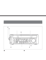
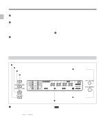
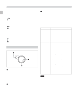
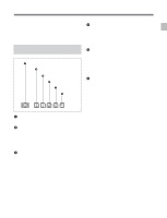
Chapter 2 Location and Function of Parts 2-1 Control Panel 3 Cassette compartment Insert an S or L cassette. 4 Remote control detector Receives the infrared signal from the supplied Remote Commander. For details on the Remote Commander, see section 4-3 "Using the Remote Commander" on page 4-6. 5 PF (programmable function)-1/2 buttons When using the Betacam SX or MPEG IMX format and settting this unit into noiseless mode, use these buttons to perform frame step playback (see page 4-3). To the PF-2 button, you can assign functions that are set in basic menu item 022, PF2 KEYSELECT. Function "tape remain time" is assigned to the PF-2 button as the factory default settings. While you are pressing the button, the remaining tape time are displayed in the display section. For details on function assignment, see the section "Menu bank operations (basic menu items B01 to B12) " on page 7-5. 6 PHONES (headphones) jack and control knob Connect stereo headphones with an impedance of 8 ohms to monitor the sound during playback. The control knob adjusts the volume. It is possible to make a setting so that the output volume from the AUDIO MONITOR connectors is controlled simultaneously. Set AUDIO MONITOR OUTPUT LEVEL, extended menu item 114, to VAR to enable the above feature. 2-1-1 Display Section 1 LTC/VITC button 2 SET/MENU button 3 AU MON SEL/DOLBY C NR button 4 SHIFT button 5 CTL/TC/UB button 6 CTL RESET button 7 FL (Fluorescent) display and indicators 1 LTC/VITC button This selects the time code displayed in the FL display in the following sequence: LTC1), VITC2). The underline for the LTC or VITC time code setting indicators lights corresponding to the selection. Note In this unit, VITC may not be displayed correctly except during normal playback. ... 1) LTC: abbreviation of Longitudinal Time code. This time code is recorded on a longitudinal track on the tape. Reading is unreliable at low speeds, and not possible at all during still playback. 2) VITC: abbreviation of Vertical Interval Time code. This time code is inserted in the vertical blanking interval and recorded on the video tracks. 2-2 Chapter 2 Location and Function of Parts
-
 1
1 -
2
-
3
-
4
-
5
-
6
-
7
-
 8
8 -
 9
9 -
 10
10 -
 11
11 -
 12
12 -
 13
13 -
 14
14 -
 15
15 -
 16
16 -
 17
17 -
 18
18 -
19
-
20
-
21
-
22
-
23
-
24
-
25
-
26
-
27
-
28
-
29
-
30
-
31
-
32
-
33
-
34
-
35
-
36
-
37
-
38
-
39
-
40
-
41
-
42
-
43
-
44
-
45
-
46
-
47
-
48
-
49
-
50
-
51
-
52
-
53
-
54
-
55
-
56
-
57
 |
 |
