Sony J30 Product Manual (J10, J10SDI, J30, and J30SDI Manual) - Page 15
Control Panel
 |
View all Sony J30 manuals
Add to My Manuals
Save this manual to your list of manuals |
Page 15 highlights
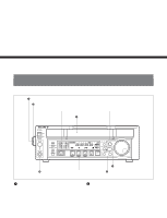
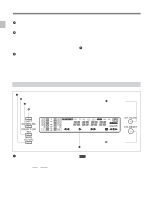
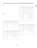
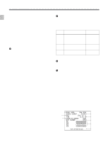
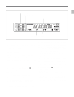
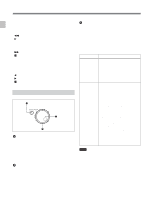
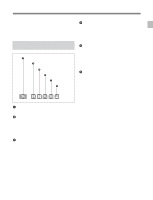
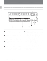
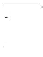
Chapter 2 Location and Function of Parts 2-1 Control Panel Press this button while holding down the SHIFT button to function the DOLBY C NR button. The DOLBY C NR indicator lights in the display section. When you are using an oxide tape, it switches the Dolby NR C-type system for analog audio on or off. When you are using a metal tape, the Dolby C NR system is automatically switched on, regardless of the setting of this switch. ON: Enables the Dolby C NR system for playback of an analog Betacam oxide tape. OFF: Disables the Dolby C NR system for playback of an analog Betacam oxide tape. The factory default setting is OFF. 4 SHIFT button Hold down this button and press the AU MON SEL/ DOLBY C NR button to enable the DOLBY C NR function. To enable the menu function, press the SET/ MENU button while holding down the SHIFT button. Press the F FWD or REW button while holding down the SHIFT button to do the forward or reverse cue-up of the shot marks 1). These marks are located before and after of the current tape position. In addition, press the PLAY button while holding down the SHIFT button to superimpose the shot data2) (when using the Betacam/Betacam SP/Betacam SX format) or UMID (when using the Digital Betacam/ MPEG IMX format) over the playback image. To clear the shot data or UMID, again press the PLAY button while holding down the SHIFT button. For details on UMID, see Chapter 5. 5 CTL/TC/UB (display switching) button This selects the time data displayed in the fluorescent display in the following sequence: CTL, TC, UB. As the display changes, the corresponding indicators over the fluorescent display also light/go off. Time data display selection and display contents Display Value displayed selection CTL Tape running time (hours, minutes, seconds, frames) computed from the CTL (control) signal recorded on the tape during playback. TC Playback time code read by the internal time code reader.a) UB User bit value inserted in the playback time code.a) Indicator status CTL indicator lights. The TC indicator lights. The UB indicator lights. a) The LTC/VITC button switches between LTC and VITC. 6 CTL RESET button Press this button to reset a CTL value displayed in the FL display area. 7 FL (Fluorescent) display and indicators These comprise a time data display, an audio monitor display and of indicators. (See the figure on next page.) ... 1) Shot marks If you use a camcorder which allows you to use shot marks, you can insert REC START marks or shot marks in the user bits area in advance for easy editing. This is called inserting shot marks. 2) Shot data The information recorded continuously during the process of shooting is called shot data. The contents of the display vary corresponding to the change of shooting conditions (e.g. changing camcorders, shooting on different dates, etc.). If there are any parts that contain no shot data by changing a shooting camcorder, the unit displays blank data. Model name Date Cassette number MODEL NAME DNW 0090 SERIAL NUMBER 010001 DATE 2001.05.11 TIME 12.55.10 CASSETTE NUMBER 0095 SHOT NUMBER 0052 ID1 AAAAAAAAAAAA ID2 BBBBBBBBBBBB ID3 CCCCCCCCCCCC ID4 DDDDDDDDDDDD TCR 23:59:59:29 Serial number Time Shot number Camera ID Time code at recording 2-4 Chapter 2 Location and Function of Parts
-
 1
1 -
2
-
3
-
4
-
5
-
6
-
7
-
8
-
9
-
 10
10 -
 11
11 -
 12
12 -
 13
13 -
 14
14 -
 15
15 -
 16
16 -
 17
17 -
 18
18 -
 19
19 -
 20
20 -
21
-
22
-
23
-
24
-
25
-
26
-
27
-
28
-
29
-
30
-
31
-
32
-
33
-
34
-
35
-
36
-
37
-
38
-
39
-
40
-
41
-
42
-
43
-
44
-
45
-
46
-
47
-
48
-
49
-
50
-
51
-
52
-
53
-
54
-
55
-
56
-
57
 |
 |
