Sony J30 Product Manual (J10, J10SDI, J30, and J30SDI Manual) - Page 29
Superimposed Character Information
 |
View all Sony J30 manuals
Add to My Manuals
Save this manual to your list of manuals |
Page 29 highlights
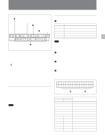
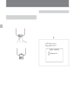
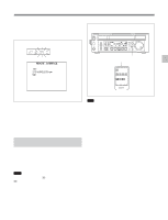
4-2 Superimposed Character Information Chapter 4 Playback 1 Types of time data Time data 2 Drop frame mark of time data 3 VITC field mark Displayed items 1 Types of time data Display CTL TCR UBR TCR. UBR. Meaning CTL counter data LTC reader time code LTC reader user bit VITC reader time code VITC reader user bit 4 Operation mode Note If the time data or user bit cannot be read correctly, they will be displayed with an asterisk. For example, "T*R", "U*R", "T*R." or "U*R.". When basic menu item 005 of the setup menu DISPLAY INFORMATION SELECT is set as anything other than OFF, the video signal output from the COMPOSITE (SUPER) output connector, SDI (SUPER) output connector (for J-10SDI/30SDI only) or DV connector contains superimposed character information (overlaid display), including time code, menu settings, or alarm messages. For details on the settings for superimposed display, see DISPLAY INFORMATION SELECT, basic menu item 005 on page 7-7, SDI OUT CHARACTER, basic menu item 027 on page 7-9, and i.LINK CHARACTER, basic menu item 030 on page 7-9. 2 Drop frame mark of time data " . ": Drop frame mode " : ": Non-drop frame mode 3 VITC field mark " " blank: When displaying Field 1 and 3 " * ": When displaying Field 2 and 4 4 Operation mode The field is divided into two blocks, A and B. • Block A: displays the operation mode. • Block B: displays the servo lock status or tape speed. Adjusting the character display The basic menu adjusts the position, size and type of the superimposed characters. For details of the basic menu, see section 7-3 "Basic Menu" on page 7-7. Note As the factory default setting, basic menu item 005, DISPLAY INFORMATION SELECT is set to OFF. Changing the setting of basic menu item 005, DISPLAY INFORMATION SELECT allows different time data to be displayed in the bottom line of the display. For details, see section 7-3 "Basic Menu" on page 7-7. A B Display Block A Block B TAPE UNTHREAD STANDBY OFF STOP F.FWD REW PLAY PLAY LOCK JOG STILL JOG FWD JOG REV SHUTTLE STILL SHUTTLE (Speed) Operation mode Cassette is not loaded. Standby off mode Stop mode Fast forward mode Rewind mode Playback mode (servo unlocked) Playback mode (servo locked) A still picture in jog mode Jog mode in forward direction Jog mode in reverse direction A still picture in shuttle mode Shuttle mode 4-5 Chapter 4 Playback
-
 1
1 -
2
-
3
-
4
-
5
-
6
-
7
-
8
-
9
-
10
-
11
-
12
-
13
-
14
-
15
-
16
-
17
-
18
-
19
-
20
-
21
-
22
-
23
-
 24
24 -
 25
25 -
 26
26 -
 27
27 -
 28
28 -
 29
29 -
 30
30 -
 31
31 -
 32
32 -
 33
33 -
 34
34 -
35
-
36
-
37
-
38
-
39
-
40
-
41
-
42
-
43
-
44
-
45
-
46
-
47
-
48
-
49
-
50
-
51
-
52
-
53
-
54
-
55
-
56
-
57
 |
 |
