Sony J30 Product Manual (J10, J10SDI, J30, and J30SDI Manual) - Page 22
Audio monitor L/R output connectors XLR - sdi manual
 |
View all Sony J30 manuals
Add to My Manuals
Save this manual to your list of manuals |
Page 22 highlights
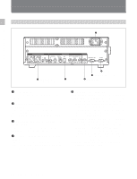
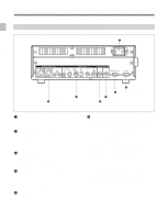
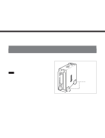
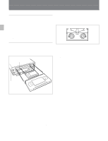
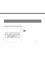
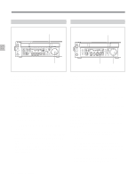
Chapter 2 Location and Function of Parts DV (i.LINK DV) output connector (IEEE1394, 6-pin): Outputs video/audio signals in DV format. When basic menu item 030, i.LINK CHARACTER, of the setup menu is set to ON and basic menu item 005, DISPLAY INFORMATION SELECT is set as anything other than OFF, the output from this connector outputs superimposed character information such as time code, menu settings, or alarm messages. Notes • Through the DV connector, only one DV device can be connected to this unit. If you intend to connect multiple DV devices, refer to the manuals of them. • The i.LINK (DV) output of this unit is used to provide materials to a computer on which nonlinear editing software is installed. You can use a Sony VTR equiped with an i.LINK (DV) connector (DVCAM series of VTRs for example) with this unit, though, the auto dubbing function and editing function will not be available. • If the unit is connected to a device equipped with a 6-pin DV jack, when you intend to disconnect or reconnect the DV cable, turn off the device and pull out the plug of its power cord from the AC outlet beforehand. If you connect or disconnect the DV cable while the device is connected to the AC outlet, highvoltage current (8 to 40 V) is output from the DV jack of the device to this unit, which may cause a malfunction. • When connecting a device that has a 6-pin DV jack to this unit, first connect the plug of the cable to the 6-pin DV jack of the device. SDI (serial digital interface) output connector: Outputs a video/audio signal in D1 format without superimposed character information. SDI (serial digital interface) (SUPER) output connector: Outputs a video/audio signal in D1 format. When basic menu item 005, DISPLAY INFORMATION SELECT, of the setup menu is set as anything other than OFF, the connector outputs the superimposed character information such as time code, menu settings, or alarm messages. 7 AUDIO MONITOR OUTPUT connectors Audio monitor (L/R) output connectors (XLR 3-pin, male): Output two (L and R) audio monitor signals according to the setting of the AU MON SEL/DOLBY C NR button on the control panel. Audio monitor (L/R) output connectors (Phono jack): Output two (L and R) audio monitor signals according to the setting of the AU MON SEL/ DOLBY C NR button on the control panel. 2-11 Chapter 2 Location and Function of Parts
-
 1
1 -
2
-
3
-
4
-
5
-
6
-
7
-
8
-
9
-
10
-
11
-
12
-
13
-
14
-
15
-
16
-
 17
17 -
 18
18 -
 19
19 -
 20
20 -
 21
21 -
 22
22 -
 23
23 -
 24
24 -
 25
25 -
 26
26 -
 27
27 -
28
-
29
-
30
-
31
-
32
-
33
-
34
-
35
-
36
-
37
-
38
-
39
-
40
-
41
-
42
-
43
-
44
-
45
-
46
-
47
-
48
-
49
-
50
-
51
-
52
-
53
-
54
-
55
-
56
-
57
 |
 |