Sony VPL-VW11HT Operating Instructions - Page 12
Connector panel, CONTROL S IN/PLUG IN POWER DC 5V - remote
 |
View all Sony VPL-VW11HT manuals
Add to My Manuals
Save this manual to your list of manuals |
Page 12 highlights
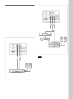
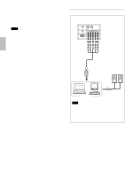
Location and Function of Controls Connector panel Left side 4 3 5 CONTROL S IN 6 VIDEO IN PLUG IN POWER TRIGGER S VIDEO VIDEO INPUT A REMOTE G/Y B/CB/PB R/CR/PR SYNC/HD VD INPUT B RS-232C (FOR SERVICE USE) G/Y B/CB/PB R/CR/PR SYNC/HD VD 1 2 6 VIDEO IN jacks Connect to external video equipment such as a VCR. S VIDEO (mini DIN 4-pin): Connects to the S video output (Y/C video output) of video equipment. VIDEO (phono type): Connects to the composite video output of video equipment. 1 INPUT A connectors G/Y, B/CB/PB, R/CR/PR, SYNC/HD, VD connectors (phono type): Connect to the RGB output of the equipment. According to the connected equipment, computer, component (Y/CB/CR), HDTV or DTV (DTV GBR, DTV YPBPR) signal is selected. 2 INPUT B connectors G/Y, B/CB/PB, R/CR/PR, SYNC/HD, VD connectors (phono type): Connect to the RGB output of the equipment. According to the connected equipment, computer, component (Y/CB/CR), HDTV or DTV (DTV GBR, DTV YPBPR) signal is selected. 3 RS-232C connector (D-sub 9-pin, female) This is a service connector. 4 TRIGGER connector (minijack) Outputs the ON or OFF condition of the unit to the external equipment. When the unit is turned off, 0 V is output and when the unit is turned on, 12 V is output. However, as power is not output, you cannot use the connector as a power source. 5 CONTROL S IN/PLUG IN POWER (DC 5V output) jack Connects to the control S out jacks of the Sony equipment. Connects to the CONTROL S OUT jack on the supplied Remote Commander when using it as a wired Remote Commander. In this case, you do not need to install the batteries in the Remote Commander, since power is supplied from this jack. If this connector is used, the Remote Commander key lamp is not turned on. 12 (GB)
-
 1
1 -
2
-
3
-
4
-
5
-
6
-
 7
7 -
 8
8 -
 9
9 -
 10
10 -
 11
11 -
 12
12 -
 13
13 -
 14
14 -
 15
15 -
 16
16 -
 17
17 -
18
-
19
-
20
-
21
-
22
-
23
-
24
-
25
-
26
-
27
-
28
-
29
-
30
-
31
-
32
-
33
-
34
-
35
-
36
-
37
-
38
-
39
-
40
-
41
-
42
-
43
-
44
-
45
-
46
-
47
-
48
-
49
-
50
-
51
-
52
-
53
-
54
-
55
-
56
-
57
-
58
-
59
-
60
-
61
-
62
-
63
-
64
-
65
-
66
-
67
-
68
-
69
-
70
-
71
-
72
-
73
-
74
-
75
-
76
-
77
-
78
-
79
-
80
-
81
-
82
-
83
-
84
-
85
-
86
-
87
-
88
-
89
-
90
-
91
-
92
-
93
-
94
-
95
-
96
-
97
-
98
-
99
-
100
-
101
-
102
-
103
-
104
-
105
-
106
-
107
-
108
-
109
-
110
-
111
-
112
-
113
-
114
-
115
-
116
-
117
-
118
-
119
-
120
-
121
-
122
-
123
-
124
 |
 |
