TASCAM Celesonic US-20x20 Owners Manual - Page 6
Names and functions of parts, Front panel
 |
View all TASCAM Celesonic US-20x20 manuals
Add to My Manuals
Save this manual to your list of manuals |
Page 6 highlights
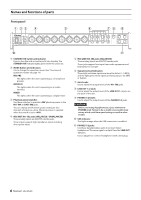
Names and functions of parts Front panel 1 STANDBY/ON switch and indicator Press to turn the unit on and to put it into standby. The STANDBY/ON indicator lights green when the unit is on. 2 MODE button and indicators Use to change the operation mode. (See "Overview of operation modes" on page 14.) MIC PRE This lights when the unit is operating as a microphone preamp. AUDIO I/F This lights when the unit is operating as an audio interface. MIXER This lights when the unit is operating as a digital mixer. 3 Phantom power switches Use these switches to provide +48V phantom power to the IN1-IN4 and IN5-IN8 jacks. You can change the Phantom power setting for four channels of inputs at a time. Phantom power is supplied when the switch is set to +48V. 4 MIC/INST IN1-IN2 jacks (BALANCED / UNBALANCED) These analog inputs are XLR/TRS combo jacks. These inputs support high impedance input, including direct guitar input. 5 MIC/LINE IN3-IN8 jacks (BALANCED) These analog inputs are XLR/TRS combo jacks. These jacks support line input from audio equipment and keyboards, for example. 6 Signal/overload indicators These light red when signals are about to distort (−1 dBFS) and the light green when signals are being input (−32 dBFS or higher). 7 Gain knobs Use to adjust the output levels of the IN1-IN8 jacks. 8 LINE OUT 1-2 knob Use to adjust the output level of the LINE OUT 1-2 jacks on the back of the unit. 9 PHONES 1/2 knobs Use to adjust the output levels of the PHONES 1/2 jacks. CAUTION Before connecting headphones to a jack, minimize its PHONES knob. Failure to do so might cause sudden loud noises, which could harm your hearing or result in other trouble. 0 USB indicator This lights orange when the USB connection is enabled. q PHONES 1/2 jacks Use these standard stereo jacks to connect stereo headphones. The same signal is output from the LINE OUT 1/2 jacks. Use an adapter to connect headphones with a mini plug. 6 TASCAM US-20x20
-
 1
1 -
 2
2 -
 3
3 -
 4
4 -
 5
5 -
 6
6 -
 7
7 -
 8
8 -
 9
9 -
 10
10 -
 11
11 -
 12
12 -
13
-
14
-
15
-
16
-
17
-
18
-
19
-
20
-
21
-
22
-
23
-
24
-
25
-
26
-
27
-
28
-
29
-
30
-
31
-
32
-
33
-
34
-
35
-
36
-
37
-
38
-
39
-
40
-
41
-
42
-
43
-
44
-
45
-
46
-
47
-
48
-
49
-
50
-
51
-
52
-
53
-
54
-
55
-
56
-
57
-
58
-
59
-
60
-
61
-
62
-
63
-
64
-
65
-
66
-
67
-
68
-
69
-
70
-
71
-
72
-
73
-
74
-
75
-
76
-
77
-
78
-
79
-
80
-
81
-
82
-
83
-
84
-
85
-
86
-
87
-
88
-
89
-
90
-
91
-
92
-
93
-
94
-
95
-
96
-
97
-
98
-
99
-
100
-
101
-
102
-
103
-
104
 |
 |
