TP-Link 3G/4G TL-MR3220 V2 User Guide - Page 80
Bandwidth Control
 |
View all TP-Link 3G/4G manuals
Add to My Manuals
Save this manual to your list of manuals |
Page 80 highlights
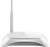
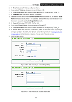
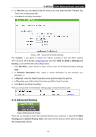
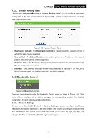
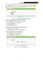
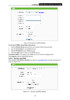
TL-MR3220 3G/4G Wireless N Router User Guide 4.12.2 System Routing Table Choose menu "Advanced Routing → System Routing Table", you can configure the system routing table in the next screen (shown in Figure 4-63). System routing table views all of the valid route entries in use. Figure 4-63 System Routing Table Destination Network - The Destination Network is the address of the network or host to which the static route is assigned. Subnet Mask - The Subnet Mask determines which portion of an IP address is the network portion, and which portion is the host portion. Gateway - This is the IP address of the gateway device that allows for contact between the Router and the network or host. Interface - This interface tells you whether the Destination IP Address is on the LAN & WLAN (internal wired and wireless networks), the WAN (Internet). 4.13 Bandwidth Control Figure 4-64 Bandwidth Control There are two submenus under the Bandwidth Control menu as shown in Figure 4-64. Click either of them, and you will be able to configure the corresponding function. The detailed explanations for each submenu are provided below. 4.13.1 Control Settings Choose menu "Bandwidth Control → Control Settings", you can configure the Egress Bandwidth and Ingress Bandwidth in the next screen. Their values you configure should be less than 100000Kbps. For optimal control of the bandwidth, please select the right Line Type and ask your ISP for the total bandwidth of the egress and ingress. -71-
-
 1
1 -
2
-
3
-
4
-
5
-
6
-
7
-
8
-
9
-
10
-
11
-
12
-
13
-
14
-
15
-
16
-
17
-
18
-
19
-
20
-
21
-
22
-
23
-
24
-
25
-
26
-
27
-
28
-
29
-
30
-
31
-
32
-
33
-
34
-
35
-
36
-
37
-
38
-
39
-
40
-
41
-
42
-
43
-
44
-
45
-
46
-
47
-
48
-
49
-
50
-
51
-
52
-
53
-
54
-
55
-
56
-
57
-
58
-
59
-
60
-
61
-
62
-
63
-
64
-
65
-
66
-
67
-
68
-
69
-
70
-
71
-
72
-
73
-
74
-
 75
75 -
 76
76 -
 77
77 -
 78
78 -
 79
79 -
 80
80 -
 81
81 -
 82
82 -
 83
83 -
 84
84 -
 85
85 -
86
-
87
-
88
-
89
-
90
-
91
-
92
-
93
-
94
-
95
-
96
-
97
-
98
-
99
-
100
-
101
-
102
-
103
-
104
-
105
-
106
-
107
-
108
-
109
 |
 |