TP-Link TL-WR840N User Guide - Page 16
Mbps Wireless N Router User Guide
 |
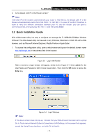
View all TP-Link TL-WR840N manuals
Add to My Manuals
Save this manual to your list of manuals |
Page 16 highlights
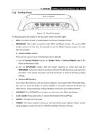
TL-WR840N 300Mbps Wireless N Router User Guide 5. Connect the power adapter to the power socket on the Router, and the other end into an electrical outlet. The Router will start to work automatically. 6. Power on your PC and Cable/DSL Modem. Figure 2-1 Hardware Installation of the TL-WR840N 300Mbps Wireless N Router Note: Figure 2-2 Wall-mount Install The diameter of the screw, 3.5mm
-
 1
1 -
2
-
3
-
4
-
5
-
6
-
7
-
8
-
9
-
10
-
 11
11 -
 12
12 -
 13
13 -
 14
14 -
 15
15 -
 16
16 -
 17
17 -
 18
18 -
 19
19 -
 20
20 -
 21
21 -
22
-
23
-
24
-
25
-
26
-
27
-
28
-
29
-
30
-
31
-
32
-
33
-
34
-
35
-
36
-
37
-
38
-
39
-
40
-
41
-
42
-
43
-
44
-
45
-
46
-
47
-
48
-
49
-
50
-
51
-
52
-
53
-
54
-
55
-
56
-
57
-
58
-
59
-
60
-
61
-
62
-
63
-
64
-
65
-
66
-
67
-
68
-
69
-
70
-
71
-
72
-
73
-
74
-
75
-
76
-
77
-
78
-
79
-
80
-
81
-
82
-
83
-
84
-
85
-
86
-
87
-
88
-
89
-
90
-
91
-
92
-
93
-
94
-
95
-
96
-
97
-
98
-
99
-
100
-
101
-
102
-
103
-
104
 |
 |
TL-WR840N
300Mbps Wireless N Router User Guide
- 7 -
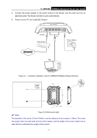
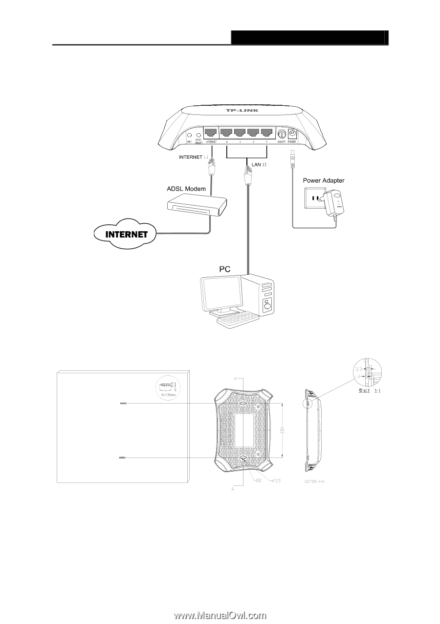
5.
Connect the power adapter to the power socket on the Router, and the other end into an
electrical outlet. The Router will start to work automatically.
6.
Power on your PC and Cable/DSL Modem.
Figure 2-1
Hardware Installation of the TL-WR840N 300Mbps Wireless N Router
Figure 2-2 Wall-mount Install
Note:
The diameter of the screw, 3.5mm<D<8mm, and the distance of two screws is 118mm. The screw
that project from the wall need around 4.5mm based, and the length of the screw need to be at
least 20mm to withstand the weight of the product.