Toshiba NB510 PLL72C-02401D Users Manual Canada; English - Page 29
Underside, Battery lock, Battery release latch, Speaker, Memory module slot
 |
View all Toshiba NB510 PLL72C-02401D manuals
Add to My Manuals
Save this manual to your list of manuals |
Page 29 highlights
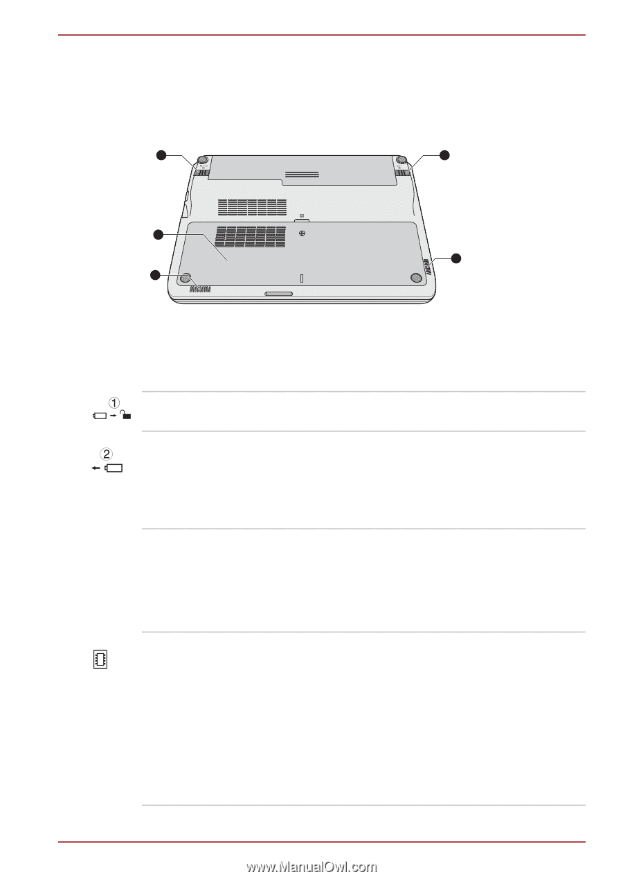
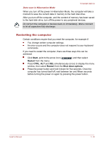
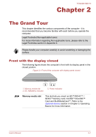
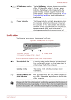
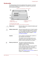
TOSHIBA NB510 Underside The following figure shows the underside of the computer. You should ensure that the display is closed before the computer is turned over to avoid causing any damage. Figure 2-5 The underside of the computer 1 2 3 4 4 1. Battery lock 2. Battery release latch 3. Memory module slot 4. Speakers* * Provided with some models. Product appearance depends on the model you purchased. Battery lock Slide the battery lock to release the battery pack ready for removal. Battery release latch Slide and hold this latch into its "Unlock" position in order to release the battery pack for removal. For more detailed information on removing the battery pack please refer to Chapter 5, Power and Power-Up Modes. Speaker Some models are equipped with a speaker on the underside of the computer. The speaker emits sound generated by your software as well as audio alarms, such as low battery condition, generated by the system. Memory module slot The memory module slot allows for the installation, replacement and removal of additional memory module. 2 GB or 4GB memory modules can be installed in the computer's memory slot. The actual amount of useable system memory will be less than the installed memory modules. Refer to the Additional memory module section in Chapter 3, Operating Basics. User's Manual 2-5
-
 1
1 -
2
-
3
-
4
-
5
-
6
-
7
-
8
-
9
-
10
-
11
-
12
-
13
-
14
-
15
-
16
-
17
-
18
-
19
-
20
-
21
-
22
-
23
-
 24
24 -
 25
25 -
 26
26 -
 27
27 -
 28
28 -
 29
29 -
 30
30 -
 31
31 -
 32
32 -
 33
33 -
 34
34 -
35
-
36
-
37
-
38
-
39
-
40
-
41
-
42
-
43
-
44
-
45
-
46
-
47
-
48
-
49
-
50
-
51
-
52
-
53
-
54
-
55
-
56
-
57
-
58
-
59
-
60
-
61
-
62
-
63
-
64
-
65
-
66
-
67
-
68
-
69
-
70
-
71
-
72
-
73
-
74
-
75
-
76
-
77
-
78
-
79
-
80
-
81
-
82
-
83
-
84
-
85
-
86
-
87
-
88
-
89
-
90
-
91
-
92
-
93
-
94
-
95
-
96
-
97
-
98
-
99
-
100
-
101
-
102
-
103
-
104
-
105
-
106
-
107
-
108
-
109
-
110
-
111
-
112
-
113
-
114
-
115
-
116
-
117
-
118
-
119
-
120
-
121
-
122
-
123
-
124
-
125
-
126
-
127
-
128
-
129
 |
 |