Tripp Lite SU10KRT3U Owner's Manual for SmartOnline Single-Phase 10kVA UPS 932 - Page 15
Maintenance
 |
View all Tripp Lite SU10KRT3U manuals
Add to My Manuals
Save this manual to your list of manuals |
Page 15 highlights
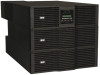
Maintenance Basic Maintenance Warning: The UPS system is very heavy. Use appropriate caution and assistance when moving or lifting it. Do not place anything on the roof of the rack enclosure. Recommended Tools: Canned Air 1 Keep the area around the UPS system clean and dry. 2 Operate the UPS system at indoor temperatures between 32° F and 104° F (between 0° C and 40° C) only. For best results, keep indoor temperatures between 62° F and 84° F (17° C and 29° C). 3 Leave at least six inches of open space at the front and rear of the UPS system for proper ventilation. 4 Periodically use canned air or a lint-free cloth to remove dust build-up from the UPS system cabinets. Use canned air rated for use with electronic components only. External Battery Pack Replacement Warning: The UPS system is very heavy. Use appropriate caution and assistance when moving or lifting it. Do not disconnect the battery pack when the UPS system is operating from battery. (The control panel's LCD screen displays "ON BATTERY MODE" and the "BATTERY" LED illuminates when the UPS system is operating from battery.) Recommended Tools: Phillips Screwdriver 1 Press the "OFF" button H on the control panel until the UPS system beeps, then release the button. Press the OFF button again to enter Bypass Mode. The control panel's LCD screen D should now display "BYPASS MODE". 2 Disconnect the male battery cable connector from the female battery connector I at the rear of the UPS power module. 3 Remove the screws from the battery pack's mounting ears. 4 Using an assistant, remove the battery pack from the rack. 5 Using an assistant, mount the new battery pack in the rack. (Refer to Mounting section if necessary.) 6 Connect the new battery cable to the female battery connector I at the rear of the UPS power module. 7 Press the control panel's "ON" button G until the UPS system beeps, then release the button. 8 The LCD screen D should display "ONLINE MODE" or "ECONOMY MODE", depending on the option selected previously. 15 6 inches (front) RACK (SIDE) 6 inches (rear) Open Space for Ventilation I UPS System Rear Panel D G E Control Panel F H 201102089 93-2982.indb 15 7/11/2011 3:49:17 PM
-
 1
1 -
2
-
3
-
4
-
5
-
6
-
7
-
8
-
9
-
 10
10 -
 11
11 -
 12
12 -
 13
13 -
 14
14 -
 15
15 -
 16
16 -
 17
17 -
 18
18 -
 19
19 -
 20
20 -
21
-
22
-
23
-
24
-
25
-
26
-
27
-
28
-
29
-
30
-
31
-
32
-
33
-
34
-
35
-
36
-
37
-
38
-
39
-
40
-
41
-
42
-
43
-
44
-
45
-
46
-
47
-
48
-
49
-
50
-
51
-
52
-
53
-
54
-
55
-
56
-
57
-
58
-
59
-
60
-
61
-
62
-
63
-
64
-
65
-
66
-
67
-
68
-
69
-
70
-
71
-
72
-
73
-
74
-
75
-
76
-
77
-
78
-
79
-
80
-
81
-
82
-
83
-
84
 |
 |
