Tripp Lite SU10KRT3U Owner's Manual for SmartOnline Single-Phase 10kVA UPS 932 - Page 6
Power Module - power protection
 |
View all Tripp Lite SU10KRT3U manuals
Add to My Manuals
Save this manual to your list of manuals |
Page 6 highlights
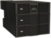
Features continued Power Module E B G F Detachable Hardwire PDU D C H A Power Module Rear Panel with Detachable PDU (Shown without wiring harness.) A Battery Pack Connector: Insert the external battery pack's male battery connector into this female battery connector. Remove the cover (not shown) for access. B Accessory Card Slot: Remove the cover to install optional accessory cards that provide the UPS system with additional functionality. The UPS network management card (SNMPWEBCARD) goes in this slot to provide remote monitoring and control via SNMP, Web or telnet. Connect an optional environmental sensor (ENVIROSENSE) to monitor temperature and humidity. Dry contact closure (RELAYIOCARD) and MODBUS (MODBUSCARD) cards are also available. C USB Port: The USB port may be used to connect your UPS to a workstation or server. It is used with Tripp Lite software and the included USB cable to monitor and manage the UPS remotely over a network and to automatically save open files and shut down equipment during a blackout. For USB communications, both DIP switches must be in the DOWN position. This will disable the RS-232 port. See Optional Connections section for more information. D Port Selection DIP Switches: When the DIP switches are both down, the USB port is active. When the DIP switches are both up, the RS-232 port is active. E RS-232 Serial Port (DB9): Connect this port to a computer with the included DB9 cable to allow the computer and UPS system to communicate. Make sure DIP switches of USB port module are both set to the UP position. This disables the USB port. See Optional Connection section for more information. F EPO (Emergency Power Off) Port: Use the included EPO cable to connect this port to a user-supplied EPO switch to enable emergency shutdown. Do not connect this port to a telephone line. See Optional Connection section for more information. G Parallel: This port allows 2 identical power modules to operate in parallel when used in conjunction with a parallel PDU. Do not connect anything to this port unless the UPS system will be operating in a parallel configuration. H Exhaust Fan: The fan cools the power module. Wiring Harness (not shown): The wiring harness comes preinstalled to the PDU. It guides and protects the wiring that connects the power module's input and output terminals to the corresponding terminals on the Transformer. Note: The harness is pre-installed to the PDU, but must be hardwired to the Transformer. 6 201102089 93-2982.indb 6 7/11/2011 3:48:54 PM
-
 1
1 -
 2
2 -
 3
3 -
 4
4 -
 5
5 -
 6
6 -
 7
7 -
 8
8 -
 9
9 -
 10
10 -
 11
11 -
 12
12 -
13
-
14
-
15
-
16
-
17
-
18
-
19
-
20
-
21
-
22
-
23
-
24
-
25
-
26
-
27
-
28
-
29
-
30
-
31
-
32
-
33
-
34
-
35
-
36
-
37
-
38
-
39
-
40
-
41
-
42
-
43
-
44
-
45
-
46
-
47
-
48
-
49
-
50
-
51
-
52
-
53
-
54
-
55
-
56
-
57
-
58
-
59
-
60
-
61
-
62
-
63
-
64
-
65
-
66
-
67
-
68
-
69
-
70
-
71
-
72
-
73
-
74
-
75
-
76
-
77
-
78
-
79
-
80
-
81
-
82
-
83
-
84
 |
 |
