Weider Pro 8500 Smith Cage Bench English Manual - Page 14
the left Side Top Frame 13.
 |
View all Weider Pro 8500 Smith Cage Bench manuals
Add to My Manuals
Save this manual to your list of manuals |
Page 14 highlights
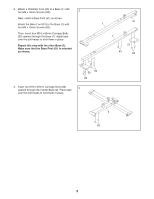
13. Insert a Guide Cap (33) upward into a Side Top Frame (13). Set the Side Top Frame on the left Weight Bar Guide (5) and insert it into the Left Support (6). Attach the Side Top Frame (13) to the left Upright (3) and the Left Support (6) with two M10 x 75mm Bolts (102), two M10 x 25mm Screws (98), four M10 Split Washers (93), and four M10 Washers (84). Do not tighten the Screws yet. Repeat this step with the other Side Top Frame (13) and the right side of the weight rack. 13 84 102 93 3 14. Insert an M10 x 68mm Bolt (90) through the left Upright (3) and the Side Top Frame (13). Hand 14 tighten an M10 Washer (84) and an M10 Locknut (79) onto the Bolt. Repeat this step with the other Side Top Frame (13) and the right side of the weight rack. 3 13 33 5 84 93 98 6 79 13 84 90 15. Make sure that the Guide Cap (33) is inside the left Side Top Frame (13). 15 Attach the Center Top Frame (14) to the Side Top Frame (13) with two M10 x 93mm Bolts (97), two 17mm Spacers (66), two M10 Washers (84), and two M10 Locknuts (79). Do not tighten the Locknuts yet. Repeat this step with the right Side Top Frame (not shown). 14 14 97 97 66 13 66 33 84 79
-
 1
1 -
2
-
3
-
4
-
5
-
6
-
7
-
8
-
 9
9 -
 10
10 -
 11
11 -
 12
12 -
 13
13 -
 14
14 -
 15
15 -
 16
16 -
 17
17 -
 18
18 -
 19
19 -
20
-
21
-
22
-
23
-
24
-
25
-
26
-
27
-
28
-
29
-
30
-
31
-
32
-
33
-
34
-
35
-
36
-
37
-
38
-
39
-
40
-
41
-
42
-
43
-
44
 |
 |
