Yamaha DSP5D Pm5dv2 / Dsp5d Editor Owner's Manual - Page 9
HPF High Pass Filter, Ø Phase, INSERT, DIRECT, COMP Compressor, EQ Equalizer, DELAY, Channel number
 |
View all Yamaha DSP5D manuals
Add to My Manuals
Save this manual to your list of manuals |
Page 9 highlights
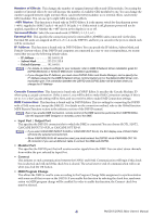
D HPF (High Pass Filter) 4 Switches the high pass filter on/off. You can drag the numeric value up or down to edit 5 the cutoff frequency. 6 7 8 E Ø (Phase) Inverts the phase of the signal after AD conversion. F INSERT 9 Switches the INSERT PATCH path between enabled/disabled. J G DIRECT Switches the output to the DIRECT OUT PATCH port between enabled/disabled. H GATE K Turns the gate on/off. The indica- L tor immediately below the button Gate= closed shows the gate's on/off setting (red) Gate= open (green) Gate= off and the open/closed status. I COMP (Compressor) Switches the compressor on/off. When the compressor is on, the GR meter immediately below the button shows the amount of gain reduction. J EQ (Equalizer) Switches the EQ on/off. The graph immediately below the button shows the approxi- mate response of the EQ. You can drag within the graph to edit the response of the EQ. M To reset the EQ to flat response, hold down the key ( key) of your computer keyboard and click the graph. K DELAY Switches the delay on/off. You can also edit the delay time by dragging the numeric value located immediately below the button up or down L Channel number Indicates the input channel number corresponding to this module. You can double- click this number to open the Selected Channel window for this channel. If you hold down your computer keyboard's key ( key) and double-click this, the Locked N window will open. M MIX SEND O P The bar graphs in this area indicate the send levels of the signals sent from the input channel to MIX buses. Pre/on (green) You can also adjust the send levels by dragging a bar Pre/off (green) graph to left or right. The bar graph display will change according to the Post/on (yellow) send position (pre/post) and on/off status of the signal Post/off (yellow) sent from the input channel to the MIX buses. NOTE • You can turn this on/off by clicking the number at the left. • For FIXED-type MIX buses, the bar graph is fixed at nominal level (0 dB), and only the on/off status is shown. N PAN Sets the panning of the signal sent from the input channel to the STEREO bus. This may be BALANCE depending on the PAN mode. O SELECT Selects input channel for which you want to perform operations. This is linked with the INPUT channel strip [SEL] keys on the PM5D panel. P CH ON (Channel on) button Switches the input channel on/off. This is linked with the INPUT channel strip CH [ON] keys on the PM5D panel. 9 PM5DV2/DSP5D Editor Owner's Manual
-
 1
1 -
2
-
3
-
 4
4 -
 5
5 -
 6
6 -
 7
7 -
 8
8 -
 9
9 -
 10
10 -
 11
11 -
 12
12 -
 13
13 -
 14
14 -
15
-
16
-
17
-
18
-
19
-
20
-
21
-
22
-
23
-
24
-
25
-
26
-
27
-
28
-
29
-
30
-
31
-
32
-
33
-
34
-
35
-
36
-
37
-
38
-
39
-
40
-
41
-
42
-
43
-
44
-
45
-
46
-
47
-
48
-
49
-
50
-
51
-
52
-
53
-
54
-
55
-
56
-
57
-
58
-
59
-
60
-
61
-
62
-
63
-
64
-
65
-
66
-
67
-
68
-
69
-
70
-
71
-
72
-
73
-
74
-
75
-
76
-
77
-
78
-
79
-
80
-
81
-
82
-
83
-
84
-
85
 |
 |
