Canon 1321B002AB User Manual - Page 74
Attaching the Roller Unit
 |
View all Canon 1321B002AB manuals
Add to My Manuals
Save this manual to your list of manuals |
Page 74 highlights
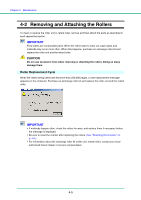
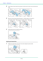
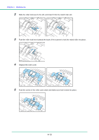
Chapter 4 Maintenance 4 Move the roller unit to the right a and then pull it out b. Attaching the Roller Unit 1 Align the cutout on the roller unit with the shaft pin on the main unit. Note If the cutout and pin do not fit, rotate the roller until the parts are properly matched. 2 Slide the roller lock lever to the left and raise the roller unit into position. 3 Push the roller lock lever up to lock the roller unit. 4-10
-
 1
1 -
2
-
3
-
4
-
5
-
6
-
7
-
8
-
9
-
10
-
11
-
12
-
13
-
14
-
15
-
16
-
17
-
18
-
19
-
20
-
21
-
22
-
23
-
24
-
25
-
26
-
27
-
28
-
29
-
30
-
31
-
32
-
33
-
34
-
35
-
36
-
37
-
38
-
39
-
40
-
41
-
42
-
43
-
44
-
45
-
46
-
47
-
48
-
49
-
50
-
51
-
52
-
53
-
54
-
55
-
56
-
57
-
58
-
59
-
60
-
61
-
62
-
63
-
64
-
65
-
66
-
67
-
68
-
 69
69 -
 70
70 -
 71
71 -
 72
72 -
 73
73 -
 74
74 -
 75
75 -
 76
76 -
 77
77 -
 78
78 -
 79
79 -
80
-
81
-
82
-
83
-
84
-
85
-
86
-
87
-
88
-
89
-
90
-
91
-
92
-
93
-
94
-
95
-
96
-
97
-
98
-
99
-
100
-
101
-
102
-
103
-
104
-
105
-
106
-
107
-
108
-
109
-
110
-
111
-
112
-
113
-
114
-
115
-
116
-
117
-
118
-
119
-
120
-
121
-
122
-
123
-
124
-
125
-
126
-
127
-
128
-
129
-
130
-
131
-
132
-
133
-
134
-
135
-
136
-
137
-
138
-
139
-
140
-
141
-
142
 |
 |

Chapter 4
Maintenance
4-10
4
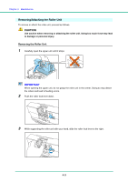
Move the roller unit to the right
a
and then pull it out
b
.
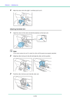
Attaching the Roller Unit
1
Align the cutout on the roller unit with the shaft pin on the main unit.
Note
If the cutout and pin do not fit, rotate the roller until the parts are properly matched.
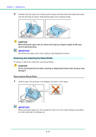
2
Slide the roller lock lever to the left and raise the roller unit into position.
3
Push the roller lock lever up to lock the roller unit.