Canon VB-S900F User Manual - Page 105
Setting the Detection Line, Setting Detection Criteria per Detection Type
 |
View all Canon VB-S900F manuals
Add to My Manuals
Save this manual to your list of manuals |
Page 105 highlights
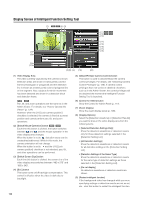
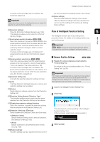
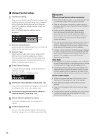
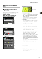
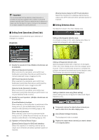
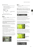
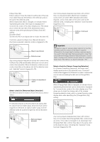
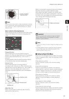
Intelligent Function Setting Tool 4 Click [Quick setting]. An outline for the detection object is drawn using a polygon with up to 32 points. If there are multiple detection objects, the area is drawn around the largest object. Configured detection area 5 Click [Restart intelligent function] again. Note • Drag the square marks (■) at each angle to change the shape of the detection line. • Click [Clear detection line] to delete a detection line. „ Setting Detection Criteria per Detection Type Specify different detection criteria for each detection type. 5 Detect criteria for [Moving Object Detection] Set detection areas where you want to detect moving objects. Admin Tools Note • Drag the square marks (■) at each angle to change the shape of the polygon. • Click [Clear] to delete the polygonal detection area. • The camera tampering detection area cannot be changed. Changing a [Rectangular] detection area into a [Polygonal] shape or changing a [Polygonal] detection area into a [Rectangular] shape Changing the shape of the detection areas already set deletes that area and switches to a new drawing setting. For [Object Size (%)], enter a value or move the slider to set the ratio of the size of an object moving in the detection area to the size of the detection area. When the ratio of an area where the camera has detected a moving object exceeds the value set for [Object Size (%)], detected mode is triggered to ON. When [Object Size (%)] is changed, an indicator frame showing the size of the object is displayed for 1 second in the center of the video display area, allowing specification of the settings while checking the size ratio. „ Setting the Detection Line Use the video display area to set the detection line. Specify a detection line consisting of a polygonal line with a maximum of 32 angles. In the video display area, click the start point of the detection line and then click the end point. To create a detection line consisting of polygonal line, click each angle in the polygonal line in order. To confirm a detection line, click any of the already set angles. The angles in a confirmed detection line can be dragged to change the shape of a detection line and lines between angles can be dragged to change the position of the detection line. Detection area Object size indicator Any moving objects detected are shown with contour lines. If a moving object is smaller than [Object Size (%)], its contour lines are white. If the moving object is larger than [Object Size (%)], its contour lines take on the same color as the detection area, indicating that "detection" mode has been triggered to ON. Contour lines of a detected moving object Detect criteria for [Abandoned Object Detection] Set areas where you want to detect abandoned objects as detection areas. 105
-
 1
1 -
2
-
3
-
4
-
5
-
6
-
7
-
8
-
9
-
10
-
11
-
12
-
13
-
14
-
15
-
16
-
17
-
18
-
19
-
20
-
21
-
22
-
23
-
24
-
25
-
26
-
27
-
28
-
29
-
30
-
31
-
32
-
33
-
34
-
35
-
36
-
37
-
38
-
39
-
40
-
41
-
42
-
43
-
44
-
45
-
46
-
47
-
48
-
49
-
50
-
51
-
52
-
53
-
54
-
55
-
56
-
57
-
58
-
59
-
60
-
61
-
62
-
63
-
64
-
65
-
66
-
67
-
68
-
69
-
70
-
71
-
72
-
73
-
74
-
75
-
76
-
77
-
78
-
79
-
80
-
81
-
82
-
83
-
84
-
85
-
86
-
87
-
88
-
89
-
90
-
91
-
92
-
93
-
94
-
95
-
96
-
97
-
98
-
99
-
 100
100 -
 101
101 -
 102
102 -
 103
103 -
 104
104 -
 105
105 -
 106
106 -
 107
107 -
 108
108 -
 109
109 -
 110
110 -
111
-
112
-
113
-
114
-
115
-
116
-
117
-
118
-
119
-
120
-
121
-
122
-
123
-
124
-
125
-
126
-
127
-
128
-
129
-
130
-
131
-
132
-
133
-
134
-
135
-
136
-
137
-
138
-
139
-
140
-
141
-
142
-
143
-
144
-
145
-
146
-
147
-
148
-
149
-
150
-
151
-
152
-
153
-
154
-
155
-
156
-
157
-
158
-
159
-
160
-
161
-
162
-
163
-
164
-
165
-
166
-
167
-
168
-
169
-
170
-
171
-
172
-
173
-
174
-
175
-
176
 |
 |
