Compaq ProLiant 1000 PCI Bus Numbering in a Microsoft Windows NT Environment - Page 25
Reviewing the Test 1 Configuration – Initial Configuration, Configuration B
 |
View all Compaq ProLiant 1000 manuals
Add to My Manuals
Save this manual to your list of manuals |
Page 25 highlights
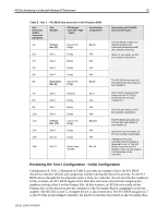
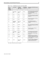
PCI Bus Numbering in a Microsoft Windows NT Environment 25 Table 8. Test 1 - PCI BIOS bus detection in the ProLiant 8000 Bus Detection Order/ Controller Discovery Slot Number PCI Bridge/ Controller Type - Test 1 Bus Number Assignment 1st Primary Host to PCI Bus 0 Bus (O) Bridge 2nd Slot 1 Empty N/A 3rd Slot 2 Empty N/A 4th Slot 3 Empty N/A 5th Slot 4 Empty N/A 6th Secondary Host to PCI Bus 6 Bus (6) Bridge 7th Slot 5 NC3131 Bus 7 8th Slot 6 Empty N/A 9th Slot 7 Empty N/A 10th Slot 8 Empty N/A 11th Tertiary Host to PCI Bus 13 Bus (13) Bridge 12th Slot 9 Empty N/A 13th Slot 10 Empty N/A 14th Slot 11 Smart Array Bus 14 4250ES Description of PCI BIOS Discovery Process The PCI BIOS assigns 0 to the Primary Bus and continues downstream with the controller discovery. Slots 1-4 are empty, no PCI bus number assignment. The PCI BIOS discovers the Secondary Bus and assigns it bus number 6. NIC in slot 5 contains a PCI bridge and the PCI BIOS increments the PCI bus number to 7. Slots 6-8 are empty, no PCI bus number assignment. The PCI BIOS discovers the Tertiary Bus and assigns it bus number 13. Slots 9 and 10 are empty, no PCI bus number assignment. Intelligent drive array controller with PCI bridge is detected in slot 11. The PCI BIOS increments the PCI number to bus 14 and assigns it to the bridge on the controller. Reviewing the Test 1 Configuration - Initial Configuration Configuration B−Test 1, illustrated in Table 8, provides an example of how the PCI BIOS discovers controller devices and assigns bus numbers during the discovery process. As the PCI BIOS moves through the bus detection order it looks for controller devices (not the slot numbers). In this example, the PCI BIOS begins at the Host Bus and moves downstream assigning bus numbers starting at bus 0 on the Primary Bus. In this scenario, no PCI devices reside on the Primary bus, so the discovery process continues to the Secondary Bus by assigning 6 as the bus number. The NC3131 in slot 5, a bridged device, is discovered next. The PCI BIOS assigns bus 7 to the PCI bus on the bridged controller, the last PCI controller discovered on the Secondary Bus. 13UK-1200A-WWEN
-
 1
1 -
2
-
3
-
4
-
5
-
6
-
7
-
8
-
9
-
10
-
11
-
12
-
13
-
14
-
15
-
16
-
17
-
18
-
19
-
 20
20 -
 21
21 -
 22
22 -
 23
23 -
 24
24 -
 25
25 -
 26
26 -
 27
27 -
 28
28 -
 29
29 -
 30
30 -
31
-
32
-
33
-
34
-
35
-
36
-
37
-
38
-
39
-
40
-
41
-
42
-
43
-
44
-
45
-
46
-
47
-
48
-
49
-
50
-
51
-
52
 |
 |