Compaq ProLiant 1000 PCI Bus Numbering in a Microsoft Windows NT Environment - Page 29
Configuration C, ProLiant DL580, Configuration C: Test 1 – Initial Configuration
 |
View all Compaq ProLiant 1000 manuals
Add to My Manuals
Save this manual to your list of manuals |
Page 29 highlights
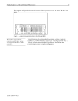
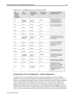
PCI Bus Numbering in a Microsoft Windows NT Environment 29 Configuration C, ProLiant DL580 Table 10 is an example of a ProLiant DL580 server set up as an original Window NT server configuration. All the controllers included in this configuration were installed in the server before Windows NT was loaded on the system. Windows NT detected network controllers in the original configuration (see Table 10) during the installation process. However, when the configuration is modified in Test 2 (see Table 11), PCI bus renumbering does occur. Configuration C: Test 1 - Initial Configuration Table 10. PCI BIOS bus detection in a ProLiant DL580-before removing and inserting NICs Bus Detection Order/ Controller Discovery 1st 2nd 3rd 4th 5th 6th 7th 8th 9th Slot Number Primary Bus (0) Slot 6 Secondary Bus (2) Slot 1 Slot 2 Slot 3 Tertiary Bus (7) Slot 4 Slot 5 PCI Bridge/ Controller Type - Test 1 Bus Number Assignment Host to PCI Bridge Bus 0 Empty N/A Host to PCI Bridge Bus 2 NC3131(bridged) Bus 3 Empty N/A NC3131 (bridged) Bus 4 Host to PCI Bridge Bus 7 Empty N/A Empty N/A Description of PCI BIOS Discovery Process The PCI BIOS assigns 0 to the Primary Bus and continues downstream with the controller discovery. Slot 6 is empty, no PCI bus number assignment. The PCI BIOS discovers the Secondary Bus and assigns it bus number 2. NIC in slot 1 contains a PCI bridge and the PCI BIOS increments the PCI bus number to 3. Slot 2 is empty, no PCI bus number assignment. Slot 3 contains a bridged NIC and assumes a bus number of 4. Finally, detection and assignment of the Tertiary Bus occurs, incrementing to 7. Since both slots on the Tertiary Bus are empty, a PCI bus number assignment does not occur for these slots. Reviewing the Test 1 Configuration Configuration C−Test 1, illustrated in Table 10, provides an example of how the PCI BIOS discovers controller devices and assigns bus numbers during the discovery process. As the PCI BIOS moves through the bus detection order it looks for controller devices (not the slot numbers). In this example, the PCI BIOS begins at the Host Bus and moves downstream assigning bus numbers starting at bus 0 on the Primary Bus. In this scenario, no PCI devices reside on the Primary bus, so the discovery process continues to the Secondary Bus and assigns 2 as the bus number. The NC3131 Fast Ethernet NIC is the first device detected. Since this controller contains a PCI bridge, the bus number increments to 3. Slot 2 contains no device, so no bus number 13UK-1200A-WWEN
-
 1
1 -
2
-
3
-
4
-
5
-
6
-
7
-
8
-
9
-
10
-
11
-
12
-
13
-
14
-
15
-
16
-
17
-
18
-
19
-
20
-
21
-
22
-
23
-
 24
24 -
 25
25 -
 26
26 -
 27
27 -
 28
28 -
 29
29 -
 30
30 -
 31
31 -
 32
32 -
 33
33 -
 34
34 -
35
-
36
-
37
-
38
-
39
-
40
-
41
-
42
-
43
-
44
-
45
-
46
-
47
-
48
-
49
-
50
-
51
-
52
 |
 |