D-Link DES-3326SRM Product Manual - Page 13
Front Panel Components, LED Indicators
 |
UPC - 790069255304
View all D-Link DES-3326SRM manuals
Add to My Manuals
Save this manual to your list of manuals |
Page 13 highlights
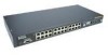
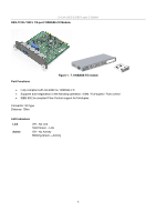
D-Link DES-3326S Layer 3 Switch Front Panel Components The front panel of the Switch consists of LED indicators, an RS-232 communication port, a slide-in module slot, and 24 (10/100 Mbps) Ethernet/Fast Ethernet ports. Figure 1 - 1. Front Panel View of the Switch as shipped (no modules are installed) • Comprehensive LED indicators display the status of the switch and the network (see the LED Indicators section below). • An RS-232 DCE console port for setting up and managing the switch via a connection to a console terminal or PC using a terminal emulation program. • A front-panel slide-in module slot for Gigabit Ethernet ports can accommodate a 2-port 1000BASE-T Gigabit Ethernet module, a 2-port 1000BASE-SX Gigabit Ethernet module, a 2-port 1000BASE-LX Gigabit Ethernet module, or a 2-port GBIC-based Gigabit Ethernet module. • Twenty-four high-performance, NWay Ethernet ports all of which operate at 10/100 Mbps with Auto-MDIX function for connections to end stations, servers and hubs. All ports can auto-negotiate between 10Mbps or 100Mbps, full or half duplex, and flow control. LED Indicators The LED indicators of the Switch include Power, Console, and Link/Act. The following shows the LED indicators for the Switch along with an explanation of each indicator. Power This indicator on the front panel should be lit during the Power-On Self Test (POST). It will light green approximately 2 seconds after the Switch is powered on to indicate the ready state of the device. Console This indicator is lit green when the Switch is being managed via out-of-band/local console management through the RS-232 console port using a straight-through serial cable. Link/Act/Speed These indicators are located to the left and right of each port. The right side indicator will light when the por has a link of 100 Mbps; the Link indicator will not light for 10 Mbps links. The LEDs blink whenever there is reception or transmission (i.e. Activity--Act) of data occurring at a port. See below for description of Stack ID LED indicator. 3
-
 1
1 -
2
-
3
-
4
-
5
-
6
-
7
-
 8
8 -
 9
9 -
 10
10 -
 11
11 -
 12
12 -
 13
13 -
 14
14 -
 15
15 -
 16
16 -
 17
17 -
 18
18 -
19
-
20
-
21
-
22
-
23
-
24
-
25
-
26
-
27
-
28
-
29
-
30
-
31
-
32
-
33
-
34
-
35
-
36
-
37
-
38
-
39
-
40
-
41
-
42
-
43
-
44
-
45
-
46
-
47
-
48
-
49
-
50
-
51
-
52
-
53
-
54
-
55
-
56
-
57
-
58
-
59
-
60
-
61
-
62
-
63
-
64
-
65
-
66
-
67
-
68
-
69
-
70
-
71
-
72
-
73
-
74
-
75
-
76
-
77
-
78
-
79
-
80
-
81
-
82
-
83
-
84
-
85
-
86
-
87
-
88
-
89
-
90
-
91
-
92
-
93
-
94
-
95
-
96
-
97
-
98
-
99
-
100
-
101
-
102
-
103
-
104
-
105
-
106
-
107
-
108
-
109
-
110
-
111
-
112
-
113
-
114
-
115
-
116
-
117
-
118
-
119
-
120
-
121
-
122
-
123
-
124
-
125
-
126
-
127
-
128
-
129
-
130
-
131
-
132
-
133
-
134
-
135
-
136
-
137
-
138
-
139
-
140
-
141
-
142
-
143
-
144
-
145
-
146
-
147
-
148
-
149
-
150
-
151
-
152
-
153
-
154
-
155
-
156
-
157
-
158
-
159
-
160
-
161
-
162
-
163
-
164
-
165
-
166
-
167
-
168
-
169
-
170
-
171
-
172
-
173
-
174
-
175
-
176
-
177
-
178
-
179
-
180
-
181
-
182
-
183
-
184
-
185
-
186
-
187
-
188
-
189
-
190
-
191
-
192
-
193
-
194
-
195
-
196
-
197
-
198
-
199
-
200
-
201
-
202
-
203
-
204
-
205
-
206
-
207
-
208
-
209
-
210
-
211
-
212
-
213
-
214
-
215
-
216
-
217
-
218
-
219
-
220
-
221
-
222
-
223
-
224
-
225
-
226
-
227
-
228
-
229
-
230
-
231
-
232
-
233
-
234
-
235
-
236
-
237
-
238
-
239
-
240
-
241
-
242
 |
 |
