D-Link DES-3326SRM Product Manual - Page 24
Switch Stacking, stacking port. See Connecting Stacked Switch Groups
 |
UPC - 790069255304
View all D-Link DES-3326SRM manuals
Add to My Manuals
Save this manual to your list of manuals |
Page 24 highlights
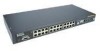
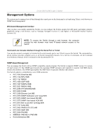
D-Link DES-3326S Layer 3 Switch Switch Stacking The optional Stacking Module allows up to thirteen DES-3326S Switches to be interconnected via their individual Stacking Modules. This forms a thirteen-switch stack that can then be managed and configured as thought the entire stack were a single switch. The switch stack is then accessed through a single IP address or alternatively, through the master switch's serial port (via the management station's console and the switch's Command Line Interface). The stacking ports are marked IN and OUT. The IEEE 1394 compliant cable must be connected from an IN port on one switch to an OUT port on the next switch in the stack. In this way, a loop is made such that all of the switches in the switch stack have the IN stacking port connected to another switch's OUT stacking port. See Connecting Stacked Switch Groups on page 24 for an illustration of a properly connected stack. Stack order can be automatically determined, the lowest MAC address is elected as the Master Switch and the remaining stack order depends on how the Switches are connected. However, it may be best to configure a Master for the group first using the CLI interface, and then connect the stack accordingly. NOTE: Stacking mode is configured using the CLI command config stacking mode. The default settings allow the switch to function as a standalone device or as a member of a stacked group. 14
-
 1
1 -
2
-
3
-
4
-
5
-
6
-
7
-
8
-
9
-
10
-
11
-
12
-
13
-
14
-
15
-
16
-
17
-
18
-
 19
19 -
 20
20 -
 21
21 -
 22
22 -
 23
23 -
 24
24 -
 25
25 -
 26
26 -
 27
27 -
 28
28 -
 29
29 -
30
-
31
-
32
-
33
-
34
-
35
-
36
-
37
-
38
-
39
-
40
-
41
-
42
-
43
-
44
-
45
-
46
-
47
-
48
-
49
-
50
-
51
-
52
-
53
-
54
-
55
-
56
-
57
-
58
-
59
-
60
-
61
-
62
-
63
-
64
-
65
-
66
-
67
-
68
-
69
-
70
-
71
-
72
-
73
-
74
-
75
-
76
-
77
-
78
-
79
-
80
-
81
-
82
-
83
-
84
-
85
-
86
-
87
-
88
-
89
-
90
-
91
-
92
-
93
-
94
-
95
-
96
-
97
-
98
-
99
-
100
-
101
-
102
-
103
-
104
-
105
-
106
-
107
-
108
-
109
-
110
-
111
-
112
-
113
-
114
-
115
-
116
-
117
-
118
-
119
-
120
-
121
-
122
-
123
-
124
-
125
-
126
-
127
-
128
-
129
-
130
-
131
-
132
-
133
-
134
-
135
-
136
-
137
-
138
-
139
-
140
-
141
-
142
-
143
-
144
-
145
-
146
-
147
-
148
-
149
-
150
-
151
-
152
-
153
-
154
-
155
-
156
-
157
-
158
-
159
-
160
-
161
-
162
-
163
-
164
-
165
-
166
-
167
-
168
-
169
-
170
-
171
-
172
-
173
-
174
-
175
-
176
-
177
-
178
-
179
-
180
-
181
-
182
-
183
-
184
-
185
-
186
-
187
-
188
-
189
-
190
-
191
-
192
-
193
-
194
-
195
-
196
-
197
-
198
-
199
-
200
-
201
-
202
-
203
-
204
-
205
-
206
-
207
-
208
-
209
-
210
-
211
-
212
-
213
-
214
-
215
-
216
-
217
-
218
-
219
-
220
-
221
-
222
-
223
-
224
-
225
-
226
-
227
-
228
-
229
-
230
-
231
-
232
-
233
-
234
-
235
-
236
-
237
-
238
-
239
-
240
-
241
-
242
 |
 |
