D-Link DES-3326SRM Product Manual - Page 152
IP Interface Configuration, , Set Up IP Interfaces
 |
UPC - 790069255304
View all D-Link DES-3326SRM manuals
Add to My Manuals
Save this manual to your list of manuals |
Page 152 highlights
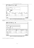
D-Link DES-3326S Layer 3 Switch Chapter 20 IP Interface Configuration To configure IP interfaces, first set up VLANs, then access the IP Interface Settings menu located in the Layer 3 - IP Networking subdirectory of the Advanced Setup folder. Set Up IP Interfaces Each VLAN must be configured prior to setting up the VLAN's corresponding IP interface. An example is presented below: Table 3. VLAN Example - Assigned Ports VLAN Name VID Switch Ports System (default) 1 Engineer 2 5, 6, 7, 8, 21, 22, 23, 24 9, 10, 11, 12 Marketing 3 Finance 4 13, 14, 15, 16 17, 18, 19, 20 Sales 5 Backbone 6 1, 2, 3, 4 25, 26 In this case, 6 IP interfaces are required, so a CIDR notation of 10.32.0.0/11 (or a 11-bit) addressing scheme will work. This addressing scheme will give a subnet mask of 11111111.11100000.00000000.00000000 (binary) or 255.224.0.0 (decimal). Using a 10.xxx.xxx.xxx IP address notation, the above example would give 6 network addresses and 6 subnets. Any IP address from the allowed range of IP addresses for each subnet can be chosen as an IP address for an IP interface on the switch. For this example, we have chosen the next IP address above the network address for the IP interface's IP Address: Table 4. VLAN Example - Assigned IP Interfaces VLAN Name System (default) Engineer Marketing Finance Sales Backbone VID Network Number 1 10.32.0.0 2 10.64.0.0 3 10.96.0.0 4 10.128.0.0 5 10.160.0.0 6 10.192.0.0 IP Address 10.32.0.1 10.64.0.1 10.96.0.1 10.128.0.1 10.160.0.1 10.192.0.1 The 6 IP interfaces, each with an IP address (listed in the table above), and a subnet mask of 255.224.0.0 can be entered into the Setup IP Interface window. To setup IP Interfaces on the switch: Go to the Advanced Setup folder, and click on the Layer 3 IP Networking link, and then click on the Setup IP Interfaces link to open the following dialog box: 142
-
 1
1 -
2
-
3
-
4
-
5
-
6
-
7
-
8
-
9
-
10
-
11
-
12
-
13
-
14
-
15
-
16
-
17
-
18
-
19
-
20
-
21
-
22
-
23
-
24
-
25
-
26
-
27
-
28
-
29
-
30
-
31
-
32
-
33
-
34
-
35
-
36
-
37
-
38
-
39
-
40
-
41
-
42
-
43
-
44
-
45
-
46
-
47
-
48
-
49
-
50
-
51
-
52
-
53
-
54
-
55
-
56
-
57
-
58
-
59
-
60
-
61
-
62
-
63
-
64
-
65
-
66
-
67
-
68
-
69
-
70
-
71
-
72
-
73
-
74
-
75
-
76
-
77
-
78
-
79
-
80
-
81
-
82
-
83
-
84
-
85
-
86
-
87
-
88
-
89
-
90
-
91
-
92
-
93
-
94
-
95
-
96
-
97
-
98
-
99
-
100
-
101
-
102
-
103
-
104
-
105
-
106
-
107
-
108
-
109
-
110
-
111
-
112
-
113
-
114
-
115
-
116
-
117
-
118
-
119
-
120
-
121
-
122
-
123
-
124
-
125
-
126
-
127
-
128
-
129
-
130
-
131
-
132
-
133
-
134
-
135
-
136
-
137
-
138
-
139
-
140
-
141
-
142
-
143
-
144
-
145
-
146
-
 147
147 -
 148
148 -
 149
149 -
 150
150 -
 151
151 -
 152
152 -
 153
153 -
 154
154 -
 155
155 -
 156
156 -
 157
157 -
158
-
159
-
160
-
161
-
162
-
163
-
164
-
165
-
166
-
167
-
168
-
169
-
170
-
171
-
172
-
173
-
174
-
175
-
176
-
177
-
178
-
179
-
180
-
181
-
182
-
183
-
184
-
185
-
186
-
187
-
188
-
189
-
190
-
191
-
192
-
193
-
194
-
195
-
196
-
197
-
198
-
199
-
200
-
201
-
202
-
203
-
204
-
205
-
206
-
207
-
208
-
209
-
210
-
211
-
212
-
213
-
214
-
215
-
216
-
217
-
218
-
219
-
220
-
221
-
222
-
223
-
224
-
225
-
226
-
227
-
228
-
229
-
230
-
231
-
232
-
233
-
234
-
235
-
236
-
237
-
238
-
239
-
240
-
241
-
242
 |
 |
