D-Link DES 6000 Product Manual - Page 14
Connecting a Terminal, Power on, Installing a Module
 |
UPC - 790069239328
View all D-Link DES 6000 manuals
Add to My Manuals
Save this manual to your list of manuals |
Page 14 highlights
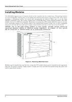
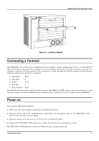
Modular Ethernet Switch User's Guide Figure 2-4. Installing a Module Connecting a Terminal The DES-6000 can perform basic switching functions without special configuration, but to use the Switch's advanced features you must first configure the unit through a terminal (a VT-100 serial data terminal or a computer running a VT-100 emulator). The connection is made through the Switch's Diagnostic RS-232 port, which is configured at the factory as follows: ♦ Baud Rate: ♦ Data Bits: ♦ Parity: ♦ Stop Bits: ♦ Flow Control: 9600 8 none 1 None The RS-232 port has a nine-socket D-shell connector with IBM-type DCE wiring, and can be connected to the terminal using an off-the-shelf RS-232 cable with the proper connectors for the terminal and the DES-6000. Power on Power up the DES-6000 as follows: 1. Make sure the power module is properly installed in the device. 2. Plug the device end of the supplied power cord firmly into the power inlet on the DES-6000's front panel of the redundant power supply. 3. Plug the outlet end of the power cord firmly into a suitable AC outlet. 4. Observe the DES-6000's LED indicators to make sure the Switch is operating correctly. The DES-6000's LED indicators operate as follows during a normal power-up: Unpacking and Setup 9
-
 1
1 -
2
-
3
-
4
-
5
-
6
-
7
-
8
-
 9
9 -
 10
10 -
 11
11 -
 12
12 -
 13
13 -
 14
14 -
 15
15 -
 16
16 -
 17
17 -
 18
18 -
 19
19 -
20
-
21
-
22
-
23
-
24
-
25
-
26
-
27
-
28
-
29
-
30
-
31
-
32
-
33
-
34
-
35
-
36
-
37
-
38
-
39
-
40
-
41
-
42
-
43
-
44
-
45
-
46
-
47
-
48
-
49
-
50
-
51
-
52
-
53
-
54
-
55
-
56
-
57
-
58
-
59
-
60
-
61
-
62
-
63
-
64
-
65
-
66
-
67
-
68
-
69
-
70
-
71
-
72
-
73
-
74
-
75
-
76
-
77
-
78
-
79
-
80
-
81
-
82
-
83
-
84
-
85
-
86
-
87
-
88
-
89
-
90
-
91
-
92
-
93
-
94
-
95
-
96
-
97
-
98
-
99
-
100
-
101
-
102
-
103
-
104
-
105
-
106
-
107
-
108
-
109
-
110
-
111
-
112
-
113
-
114
-
115
-
116
-
117
-
118
-
119
-
120
-
121
-
122
-
123
-
124
-
125
-
126
-
127
-
128
-
129
-
130
-
131
-
132
-
133
-
134
-
135
-
136
-
137
-
138
-
139
 |
 |
