D-Link DES 6000 Product Manual - Page 20
LED Indicators, Power Supply Modules
 |
UPC - 790069239328
View all D-Link DES 6000 manuals
Add to My Manuals
Save this manual to your list of manuals |
Page 20 highlights
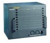
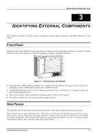
Modular Ethernet Switch User's Guide Power Supply Modules ♦ Dual power modules design with current sharing design ♦ Full redundant feature design to ensure continuous operation ♦ If one power module failed, the other will take over all current supply automatically. ♦ Hot-swappable/Hot-pluggable capability ♦ Power management functions ♦ Input: 90 ~ 264 VAC, 47 ~ 63Hz ♦ Output: 3.3V: 4A ~ 60A ♦ 12V: 0.1A ~ 2A LED Indicators The LED indicators of the Switch include CPU Status, Console, Power OK, and Utilization. The following shows the LED indicators for the Switch along with an explanation of each indicator. Figure 3-8. The Switch LED indicators ♦ CPU Status This leftmost indicator on the front panel displays the current status of the switch. The LED will blink while the Power-On Self-Test (POST) is running during startup. It will light a steady green after the POST test to indicate the switch is powered on and operating properly. It will light amber when an error occurs during startup and the switch is therefore not functioning. ♦ Console This indicator is lit green when the switch is being managed through the embedded console management program. The console program is accessed either through the out-of-band RS-232 console port using a straight-through serial cable or in-band via Telnet. When a secured connection is established, this LED is lit. The indicator blinks when the console RS-232 is accessed. ♦ Power OK This indicator lights green when the CPU module of the switch is receiving power and functioning properly. ♦ Utilization These indicators display the percentage of utilization on the CPU in the switch. Identifying External Components 15
-
 1
1 -
2
-
3
-
4
-
5
-
6
-
7
-
8
-
9
-
10
-
11
-
12
-
13
-
14
-
 15
15 -
 16
16 -
 17
17 -
 18
18 -
 19
19 -
 20
20 -
 21
21 -
 22
22 -
 23
23 -
 24
24 -
 25
25 -
26
-
27
-
28
-
29
-
30
-
31
-
32
-
33
-
34
-
35
-
36
-
37
-
38
-
39
-
40
-
41
-
42
-
43
-
44
-
45
-
46
-
47
-
48
-
49
-
50
-
51
-
52
-
53
-
54
-
55
-
56
-
57
-
58
-
59
-
60
-
61
-
62
-
63
-
64
-
65
-
66
-
67
-
68
-
69
-
70
-
71
-
72
-
73
-
74
-
75
-
76
-
77
-
78
-
79
-
80
-
81
-
82
-
83
-
84
-
85
-
86
-
87
-
88
-
89
-
90
-
91
-
92
-
93
-
94
-
95
-
96
-
97
-
98
-
99
-
100
-
101
-
102
-
103
-
104
-
105
-
106
-
107
-
108
-
109
-
110
-
111
-
112
-
113
-
114
-
115
-
116
-
117
-
118
-
119
-
120
-
121
-
122
-
123
-
124
-
125
-
126
-
127
-
128
-
129
-
130
-
131
-
132
-
133
-
134
-
135
-
136
-
137
-
138
-
139
 |
 |
