D-Link DWS-3250 Product Manual
D-Link DWS-3250 - xStack Switch - Stackable Manual
 |
UPC - 790069289996
View all D-Link DWS-3250 manuals
Add to My Manuals
Save this manual to your list of manuals |
D-Link DWS-3250 manual content summary:
- D-Link DWS-3250 | Product Manual - Page 1
Web/Installation Guide Product Model: TM DWS/DXS-3200 Series Layer 2+ Stackable Gigabit Ethernet Switches with optional XG uplinks Release 2.0 ©Copyright 2006. All rights reserved. - D-Link DWS-3250 | Product Manual - Page 2
DXS/DWS-3227/3227P, DXS/DWS-3250 User Guide Overview 7 Intended Audience...8 Device Description ...9 Viewing the Device ...9 DXS-3250/DWS Front Panel ...9 DXS/DWS-3227 Front Panel ...10 DXS/DWS-3227P Front Panel...10 Back Panels...11 Ports the Device ...30 Connecting the Switch to a Terminal ...30 - D-Link DWS-3250 | Product Manual - Page 3
DXS/DSW 3200 Series User Guide Initial Configuration ...35 Advanced the D-Link Embedded Web Interface 52 Understanding the D-Link Embedded Web Interface 54 Device Representation...55 Using the D-Link Embedded Web Stacking Members...74 Switching the Stacking Master ...74 Configuring Stacking ...75 Page - D-Link DWS-3250 | Product Manual - Page 4
...103 Configuring Traffic Control...108 Defining DOS Protection Security 113 Configuring Ports ...115 Viewing Port Properties ...118 Aggregating Ports ...121 Configuring LACP...122 Defining LAG Members ...124 Configuring VLANs ...125 Defining VLAN Properties...126 Defining VLAN Membership - D-Link DWS-3250 | Product Manual - Page 5
DXS/DSW 3200 Series User Guide Viewing WLAN Stations ...169 Configuring IP Information 171 Configuring IP Interfaces...171 Defining IP Addresses ...172 Defining Default Gateways ...174 Configuring DHCP ...175 Configuring ARP ... - D-Link DWS-3250 | Product Manual - Page 6
Service 237 Quality of Service Overview ...238 VPT Classification Information...238 CoS Services ...257 Downloading System Files ...258 Firmware Download...258 Configuration Download ...259 270 Managing Device Diagnostics 273 Configuring Port Mirroring ...274 Viewing Integrated Cable Tests - D-Link DWS-3250 | Product Manual - Page 7
DXS/DSW 3200 Series User Guide Configuring System Time... Resetting Interface Statistics Counters 297 Viewing Port Utilization Statistics...298 Viewing Etherlike B, Troubleshooting 333 Problem Management...334 Troubleshooting Solutions...334 Contacting D-Link Technical Support 337 Warranty - D-Link DWS-3250 | Product Manual - Page 8
Preface DXS/DWS-3227/3227P, DXS/DWS-3250 User Guide Overview Preface The Embedded Web System (EWS) is a network management system. The D-Link Embedded Web Interface configures, monitors, and troubleshoots network devices from a remote web browser. The D-Link Embedded Web Interface web pages are easy - D-Link DWS-3250 | Product Manual - Page 9
DXS/DWS 3200 Series User Guide • Section 18, Configuring Quality of Service - Provides information about configuring Quality of Service on the device. • Section 19, Managing System Files - Provides information about downloading, uploading, and copying system files. • Section 20, Managing System Logs - D-Link DWS-3250 | Product Manual - Page 10
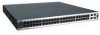
descriptions for the following: • DXS-3250/DWS Front Panel • DXS/DWS-3227 Front Panel • DXS- 3227P Front Panel • Back Panels DXS-3250/DWS Front Panel The D-Link DXS/DWS-3250 is a 48 port Gigabit Ethernet Managed Switch. The device contains 48 gigabit network ports and 4 SFP Ports on the front panel - D-Link DWS-3250 | Product Manual - Page 11
front panel there are the Port activity LEDs on each port with the system LEDs displayed separately. DXS/DWS-3227P Front Panel The D-Link DXS-3227P is a 24 port Gigabit Ethernet Managed Switch. The device contains 24 gigabit network ports, 4 SFP ports and 1XFP 10G port on the front panel for network - D-Link DWS-3250 | Product Manual - Page 12
DXS-3227 front panel: Figure 3: DXS/DWS-3227P Front Panel Device Description Viewing the Device The device front panel is configured as follows: • 24 Gigabit Ethernet ports - RJ-45 ports designated as 10/100/1000Base-T . The RJ-45 ports are desig- nated as ports Ports 1-24. • RS-232 Console port - D-Link DWS-3250 | Product Manual - Page 13
The device contains a 1000 Base-TX Gigabit 24/48 port. The port is an RJ-45 port which supports half- and fullduplex mode 10/100/1000 Mbps. 10G XFP Fiber port 10Gigabit XFP fiber port. One fixed in DXS/DWS-3227/3227P models. Optional Modules The 3200 series have module bays located on the back panel - D-Link DWS-3250 | Product Manual - Page 14
for bi-directional communication over multimode optical fiber, designed for high-speed Fiber Channel data links. The SFP port is designated as 1000Base-X. The SFP (mini-GBIC) port can be removed and inserted as required. The following figure illustrates the mini-GBIC insertion. The following figure - D-Link DWS-3250 | Product Manual - Page 15
DXS/DWS 3200 Series User Guide Figure 8: Inserting an SFP into the Device RS-232 Console Port The RS-232 port is an asynchronous serial console port supporting the RS-232 electrical specification. The port is used to connect the device to a console managing the device. This interface configuration - D-Link DWS-3250 | Product Manual - Page 16
Figure 9: Stacking Kit (Optional) Device Description Ports Description Figure 10: Inserting a Module Into a Device To insert a module into a device: 1. Release bay cover bolts. 2. Remove bay cover. 3. Carefully Insert module into its proper - D-Link DWS-3250 | Product Manual - Page 17
contains the various cable specification for the DXS/DWS-3200 series: Table 1: DXS-3250/DXS-3227P Cables and Optical Modules Specifications Cable Type 1000Base-T 10G CX-4 1000BASE-LX 1000BASE-SX 1000BASE-LH 1000BASE-ZX 10Gigabit - XFP Please refer to the D-Link datasheet for DEM-421XT and DEM - D-Link DWS-3250 | Product Manual - Page 18
on the left side of the device. The following figure illustrates the port LEDs: Figure 11: DXS-3227 1000Base-T Gigabit Ethernet RJ-45 Port LEDs The RJ-45 ports on both devices have two LEDs, one for speed, and one for Link /activity. The LED indications are described in the following table: Table - D-Link DWS-3250 | Product Manual - Page 19
DXS/DWS 3200 Series User Guide SFP LEDs The following figure illustrates the port LEDs. Figure 12: SFP LEDs The Fiber ports each have one LED. The LED indications are described in the following table: Table 3: SFP LED Indications LED Indication Green Flashing Green Off Description A link is - D-Link DWS-3250 | Product Manual - Page 20
described in the following table: Table 4: System's LED Indications LED Description PWR FAN Fault RPS P49/P50 (DXS/DWS-3250) - Link/Act for XG port P25/P26/P27 (DXS/DWS-3227/3227P) Link/Act for XG port MS PoE LED Indication Green Off Red Off Red Flashing Red Green Off Green Green Green Flashing - D-Link DWS-3250 | Product Manual - Page 21
DXS/DWS 3200 Series User Guide Table 4: System's LED Indications LED Description LED Indication Amber Off alternating Green and Amber Description An error is occurred at this port There is no error at this port An error is occurred at this port Cable, Port Interface The switching port can connect - D-Link DWS-3250 | Product Manual - Page 22
, and Pinout Information The following table describes the pin allocation Table 6: CX-4 Port Pin Connections Pin Use S1 Rx 0+ 2 Rx 0- 3 Rx 1+ 4 Rx 1- 5 Rx 2+ 6 Rx 2- 7 Rx 3+ 8 Rx 3- 9 Tx 3- 10 Tx 3+ 11 Tx 2- 12 Tx 2+ 13 Tx 1- 14 Tx 1+ 15 - D-Link DWS-3250 | Product Manual - Page 23
GND 6 N/A 7 N/A 8 N/A 9 N/A Physical Dimensions The device has the following physical dimensions: DXS/DWS - 3250 / DXS/DWS - 3227P • Width: 440 mm (17.32 inch) • Depth: 430mm (16.93 inch) • Height: 44 mm (1.77 inch) DXS/DWS - 3227 • Width: 440 mm (17.32 inch) • Depth: 310 mm (12.20 inch - D-Link DWS-3250 | Product Manual - Page 24
Device Description Physical Dimensions This page is left blank intentionally. Page 23 - D-Link DWS-3250 | Product Manual - Page 25
DXS/DWS 3200 Series User Guide Page 24 - D-Link DWS-3250 | Product Manual - Page 26
lighting bolt may cause electrical shock. These components are to be serviced by trained service technicians only. • Ensure the power cable, extension cable, cool before removing covers or touching internal equipment. • Ensure the switch does not overload the power circuits, wiring, and over-current - D-Link DWS-3250 | Product Manual - Page 27
DXS/DWS 3200 Series User Guide Site Requirements The device is placed on a table-top. Before installing the unit, verify that the location product for damage. Report any damage immediately. If any item is found missing or damaged, please contact your local D-Link reseller for replacement. Page 26 - D-Link DWS-3250 | Product Manual - Page 28
Shelf Installation • Rack Installation Desktop or Shelf Installation When installing the switch on a desktop or shelf, the rubber feet included with the at each corner of the device. Ensure the surface is be able to support the weight of the device and the device cables. To install the device on - D-Link DWS-3250 | Product Manual - Page 29
DXS/DWS 3200 Series User Guide Notes • Disconnect all cables from the unit before mounting the device in a rack or cabinet. • When mounting multiple devices into a rack, mount the devices from - D-Link DWS-3250 | Product Manual - Page 30
Figure 20: Mounting Device in a Rack Mounting Device Installing the Device 5. Secure the unit to the rack with the rack screws (not provided). Fasten the lower pair of screws before the upper pair of screws. This ensures that the weight of the unit is evenly distributed during installation. Ensure - D-Link DWS-3250 | Product Manual - Page 31
DXS/DWS 3200 Series User Guide Connecting the Device This section describes how to connect the device, and includes the following sections: • Connecting the Switch to a Terminal • AC Power Connection Connecting the Switch to a Terminal The device is connected to a terminal through an console port on - D-Link DWS-3250 | Product Manual - Page 32
-level operational mode that both ports can support If connecting a port of the switch to the network interface card (NIC) of a terminal that does not support auto-negotiation or is not set to auto-negotiation, both the device port and the NIC must be manually set with the Web browser interface - D-Link DWS-3250 | Product Manual - Page 33
DXS/DWS 3200 Series User Guide Device Port Default Settings The following table describes the device port default settings:. Table 8: Device Port Default Settings Function Port speed and mode Port terminal already connected, the switch goes through Power On Self If a critical problem is detected, - D-Link DWS-3250 | Product Manual - Page 34
Configuration Booting the Switch As the switch boots, the bootup appears at the end of POST (see the last lines) indicates that no problems were encountered during boot. During boot, the Startup menu can be accessed if numbered system ports and their states (up or down) are displayed. Page 33 - D-Link DWS-3250 | Product Manual - Page 35
DXS/DWS 3200 Series User Guide 43:13 HW version is Base Mac address is: 00:00:b0:24:11:80 Dram size is: LINK-I-Up: Vlan 1 01-Jan-200x 01:01:23 %LINK-W-Down: e4 . . . 01-Jan-200x 01:01:23 %LINK-W-Down: e46 01-Jan-200x 01:01:23 %LINK-W-Down: e47 01-Jan-200x 01:01:23 %LINK-W-Down: e48 After the switch - D-Link DWS-3250 | Product Manual - Page 36
ip interface" command. The commands to configure the device are port specific. To manage the switch from a remote network, a static route must be configured, 255.255.255.0 Console(config-if)# exit Console# ip route 192.168.2.0/24 100.1.1.33 Note 100.1.1.33 is the IP address of the next hop that - D-Link DWS-3250 | Product Manual - Page 37
DXS/DWS 3200 Series User Guide User Name The device is SNMP-compliant and contains an SNMP agent that supports a set of standard and private MIB variables. Developers of management management access to the switch is disabled if no community strings exist. Note The device switch is delivered with no - D-Link DWS-3250 | Product Manual - Page 38
Target Address Type Community Version Udp Filter To Retries Port name Sec ------ Version 3 notifications Target Address Type same access rights. Common practice is to use two community strings for the switch one (public community) with read-only access and the other (private community) - D-Link DWS-3250 | Product Manual - Page 39
DXS/DWS 3200 Series User Guide console# configure console(config)# snmp-server community priate client. To retrieve an IP address from a DHCP server, perform the following steps: 1. Select and connect any port to a DHCP server or to a subnet that has a DHCP server on it, in order to retrieve the - D-Link DWS-3250 | Product Manual - Page 40
it. The device then enables DHCP as instructed in the new configuration file, and the DHCP instructs it to reload the same file again. Receiving an IP Address From a BOOTP Server The standard BOOTP protocol is supported and enables the switch to automatically download its IP host configuration from - D-Link DWS-3250 | Product Manual - Page 41
DXS/DWS 3200 Series User Guide The following example illustrates the process: Console> enable Console password entered. Configuring Security Passwords Introduction The security passwords can be configured for the following services: • Console • Telnet • SSH • HTTP • HTTPS Passwords are user-defined. - D-Link DWS-3250 | Product Manual - Page 42
(config)# ip https certificate 1 When initially enabling an http or https session, enter admin for user name and user1 for password. Note HTTP and HTTPS services require level 15 access and connect directly to the configuration level access. Page 41 - D-Link DWS-3250 | Product Manual - Page 43
DXS/DWS 3200 Series User Guide Software Download and Reboot Software Download through XModem This section contains instructions 1. Enter the command "xmodem:image". The switch is ready to receive the file via the address is configured on one of the device ports and pings can be sent to a TFTP server - D-Link DWS-3250 | Product Manual - Page 44
server: 1. Ensure that an IP address is configured on one of the device ports and pings can be sent to a TFTP server. 2. Ensure that the file tftp://{tftp address}/{file name} boot" to copy the boot image to the switch. The following is an example of the information that appears: Console# copy tftp - D-Link DWS-3250 | Product Manual - Page 45
DXS/DWS 3200 Series User Guide 5. Enter the command "reload". The following message is displayed: Console# reload This command will reset the whole system and disconnect your current session. Do you want to continue (y/n)[n]? 6. Enter "Y" to reboot the switch that no problems were encountered during - D-Link DWS-3250 | Product Manual - Page 46
Configuring Stacking 6. On the Startup Menu, press "6". The following Stack Menu is displayed: Stack menu [1] Set unit number in stack [2] Change stacking ports [3] Stack info [4] Back Enter your choice or press 'ESC' to exit: 7. To Set a unit number press "1" on the Stack Menu. The following - D-Link DWS-3250 | Product Manual - Page 47
DXS/DWS 3200 Series User Guide 16. From the Startup menu: 1. During the boot process, after the first part of the POST is completed press or within seconds (default), the switch times out and the device continues to load normally. Only technical support personnel can operate the - D-Link DWS-3250 | Product Manual - Page 48
3. Enter config as the name of the flash file. The configuration is erased and the device reboots. 4. Perform the switch's initial configuration. Erase FLASH Sectors For troubleshooting purposes, the flash sectors may need to be erased. If the flash is erased, all software files must be downloaded - D-Link DWS-3250 | Product Manual - Page 49
DXS/DWS 3200 Series User Guide DXS- model into a DWS model with WLAN support , the user must enter a Licence key. The following section describes the procedures for entering a Licence Key. As the switch last lines) indicates that no problems were encountered during boot. To - D-Link DWS-3250 | Product Manual - Page 50
Initial Configuration Startup Menu Functions The following Licence Menu is displayed: License menu [1] Add license [2] Remove license [3] Show license [4] Back Enter your choice or press 'ESC' to exit: 3. From the License Menu, press "1". The following prompt is displayed: Enter licence: 4. Enter - D-Link DWS-3250 | Product Manual - Page 51
DXS/DWS 3200 Series User Guide This page is left blank intentionally. Page 50 - D-Link DWS-3250 | Product Manual - Page 52
Getting Started This section provides an introduction to the user interface, and includes the following topics: • Starting the D-Link Embedded Web Interface • Understanding the D-Link Embedded Web Interface • Using Screen and Table Options • Resetting the Device • Logging Off from the Device Page 51 - D-Link DWS-3250 | Product Manual - Page 53
DXS/DWS 3200 Series User Guide Starting the D-Link Embedded Web Interface Notes • Disable the popup blocker before beginning device configuration using the EWS. This section contains information on starting the D-Link Embedded Web interface. To access the D-Link user interface: 1. Open an Internet - D-Link DWS-3250 | Product Manual - Page 54
Getting Started Starting the D-Link Embedded Web Interface Notes • The screen captures in this Guide represent the 48 port device. The Web pages in the 24 port device may vary slightly. Figure 22: D-Link Embedded Web Interface Home Page Page 53 - D-Link DWS-3250 | Product Manual - Page 55
DXS/DWS 3200 Series User Guide Understanding the D-Link Embedded Web Interface The D-Link Embedded Web Interface Home Page contains the following views: • Port LED Indicators - Located at the top of the home page, the port LED indicators provide a visual repre- sentation of the ports on the D-Link - D-Link DWS-3250 | Product Manual - Page 56
Zoom View 5 D-Link Web Interface Information Tabs graphic of the device on which D-Link Web Interface runs. Provide access to Link Embedded Web Interface Management Buttons - Provides instructions for adding, modifying, and deleting configuration parameters. Device Representation The D-Link - D-Link DWS-3250 | Product Manual - Page 57
DXS/DWS 3200 Series User Guide Using the D-Link Embedded Web Interface Management Buttons Configuration Management buttons and icons provide an easy method of configuring device information, and include the following: Table 10: Button D-Link Web Interface Configuration Buttons Button Name Clear - D-Link DWS-3250 | Product Manual - Page 58
3. Define the fields. 4. Click . The configuration information is saved, and the device is updated. Modifying Configuration Information 1. Open The D-Link Embedded Web Interface page. 2. Select a table entry. 3. Click . A modification page, such as the IP Interface Settings Page opens: Page - D-Link DWS-3250 | Product Manual - Page 59
DXS/DWS 3200 Series User Guide Figure 26: IP Interface Settings Page 4. Modify the fields. 5. Click . The fields are modified, and the information is saved to the device. Deleting Configuration Information 1. Open The D-Link Embedded Web Interface page. 2. Select a table row. 3. Select the - D-Link DWS-3250 | Product Manual - Page 60
from being lost, save all changes from the running configuration file to the startup configuration file before resetting the device. For instructions, see Copying Files. To reset the device: 1. Click System > General > Reset. The Reset page opens. Figure 27: Reset Page 2. Click . A confirmation - D-Link DWS-3250 | Product Manual - Page 61
DXS/DWS 3200 Series User Guide Logging Off from the Device 1. Click 2. Click . The Logout Page opens. . The D-Link Embedded Web Interface Home Page closes. Page 60 - D-Link DWS-3250 | Product Manual - Page 62
contains parameters for configuring general device information, including the system name, location, and contact, the system MAC Address, System Object ID, System Up Time, and MAC addresses, and both software, boot, and hardware versions. To define the general system information: 1. Click System - D-Link DWS-3250 | Product Manual - Page 63
DXS/DWS 3200 Series User Guide • System Object ID - Displays the vendor's authoritative identification of the example, 41 days, 2 hours, 22 minutes and 15 seconds. • Base MAC Address - Displays the device MAC address. • Hardware Version - Displays the installed device hardware version number. • - D-Link DWS-3250 | Product Manual - Page 64
The Mode Page contains the following field: • Enable Jumbo Frames - Indicates if Jumbo Frames are enabled on the device. Maximum packet length supported is 10Kb. The possible field values are: - Checked - Enables Jumbo Frames on the device. - Unchecked - Disables Jumbo Frames on the device. 2. Check - D-Link DWS-3250 | Product Manual - Page 65
DXS/DWS 3200 Series User Guide This page is left blank intentionally. Page 64 - D-Link DWS-3250 | Product Manual - Page 66
power from the device power supplies, for example IP phones. Powered Devices are connected to the device via Ethernet ports. PoE is enabled for the DXS-3227P only. This section includes the following topics: • Defining PoE System Information • Displaying and Editing PoE System Information Page 65 - D-Link DWS-3250 | Product Manual - Page 67
DXS/DWS 3200 Series User Guide Defining PoE System Information The PoE Properties Page contains system PoE information for enabling PoE on the device, monitoring the current power usage, and enabling - D-Link DWS-3250 | Product Manual - Page 68
Managing Power over Ethernet Devices Defining PoE System Information 3. Define the Unit No. and the System Usage Threshold field. 4. Check the Traps checkbox. 5. Click . The system PoE parameters are defined, and the device is updated. Page 67 - D-Link DWS-3250 | Product Manual - Page 69
DXS/DWS 3200 Series User Guide Displaying and Editing PoE System Information The PoE Interface and stops the power supply to the device using the PoE module. • Operation Status - Indicates if the port is enabled to work on PoE. The possible field values are: - On - Indicates the device is delivering - D-Link DWS-3250 | Product Manual - Page 70
not be read. • Priority Level - Determines the port priority if the power supply is low. The port power priority is used if the power supply is low Provides a user-defined powered device description. The field can contain up to 24 char- acters. 2. Click . The PoE Interface Edit Page opens: Figure - D-Link DWS-3250 | Product Manual - Page 71
DXS/DWS 3200 Series User Guide • Invalid Signature Counter - Indicate the times an invalid signature was received. Signatures are the means by which the powered device identifies itself to the PSE. - D-Link DWS-3250 | Product Manual - Page 72
(CLI) Devices support stacking up to eight units per stack, or can operate as stand-alone units. During the Stacking setup, one switch is selected as detects and reconfigures the ports with minimal operational impact in the event of: • Unit Failure • Inter-unit Stacking Link Failure • Unit Insertion - D-Link DWS-3250 | Product Manual - Page 73
DXS/DWS 3200 Series User Guide packet continues through the stack until it reaches the destination port. The system automatically discovers the optimal path on which to becomes non-functional, or a link is severed. In a stack, the system automatically switches to a Stacking Failover topology without - D-Link DWS-3250 | Product Manual - Page 74
enabled stacking members are present, and one has been manually configured as the Stacking Master, the manually configured member is elected Stacking Master. • If two learned MAC addresses are not saved. Each port in the stack has a specific Unit ID, port type, and port number, which is part of - D-Link DWS-3250 | Product Manual - Page 75
DXS/DWS 3200 Series User Guide • Units toggle between Stacking Mode and Links from the Stacking Master to the stacking members fails. • A soft switchover is performed with either via web interface or the CLI. Switching between the Stacking Master and the Secondary Master results in a limited service - D-Link DWS-3250 | Product Manual - Page 76
unit order based on the Unit IDs. • Neighbor 1 - Displays the selected stacking unit's neighbor. • Neighbor 2 - Displays the selected stacking unit's neighbor. • Switch Stack Control from Unit 2 to Unit 1 - Changes the stack control from the Backup Master to the Stack Master. The possible field - D-Link DWS-3250 | Product Manual - Page 77
DXS/DWS 3200 Series User Guide This page is left blank intentionally. Page 76 - D-Link DWS-3250 | Product Manual - Page 78
8. Configuring Device Security This section provides access to security pages that contain fields for setting security parameters for ports, device management methods, users, and server security. This section contains the following topics: • Configuring Management Security • Configuring Network - D-Link DWS-3250 | Product Manual - Page 79
DXS/DWS 3200 Series User Guide Configuring Management Security This section provides information for configuring device management security. This section includes the following topics: • Configuring Authentication Methods • Configuring Passwords Configuring Authentication - D-Link DWS-3250 | Product Manual - Page 80
to different management methods may differ between user groups. For example, User Group 1 can access the switch module only via an HTTPS session, while User Group 2 can access the switch module via both HTTPS and Telnet sessions. The Access Profile Page contains the currently configured access - D-Link DWS-3250 | Product Manual - Page 81
DXS/DWS 3200 Series User Guide - Unchecked - Maintains the access profiles. 2. Click . The Defines the interface on which the access profile is defined. The possible field values are: - Port - Specifies the port on which the access profile is defined. - LAG - Specifies the LAG on which the access - D-Link DWS-3250 | Product Manual - Page 82
Configuring Device Security Configuring Management Security • Source IP Address - Defines the interface source IP address to which the access profile applies. The Source IP Address field is valid for a subnetwork. 3. Define the Access Profile Name, Rule Priority, Management Method, Interface, - D-Link DWS-3250 | Product Manual - Page 83
DXS/DWS 3200 Series User Guide Defining Profile Rules Access profiles can contain up to 128 rules that determine which users can manage the switch to which the rule applies. The possible field values are: - Port - Attaches the rule to the selected port. - LAG - Attaches the rule to the selected LAG. - D-Link DWS-3250 | Product Manual - Page 84
Configuring Device Security Configuring Management Security - Telnet - Assigns Telnet access to the rule. If selected, users accessing the device using Telnet meeting access profile criteria are permitted or denied access to the device. - Secure Telnet (SSH) - Assigns SSH access to the rule. If - D-Link DWS-3250 | Product Manual - Page 85
DXS/DWS 3200 Series User Guide To modify a Profile Rule: 1. Click System > Management Security > Authentication > Profile Rules. The Access Profile Page opens 2. Click . The Profile Rules Setting Page opens: 3. Modify the - D-Link DWS-3250 | Product Manual - Page 86
Configuring Device Security Configuring Management Security Defining Authentication Profiles Authentication profiles allow network administrators to assign authentication methods for user authentication. User authentication can be performed either locally or on an external server. User - D-Link DWS-3250 | Product Manual - Page 87
DXS/DWS 3200 Series User Guide 2. Click . The Add Authentication Profile Page opens. Figure 40: Add Authentication Profile Page 3. Define the Profile Method, Profile Name and Authentication Methods fields. 4. Click . The - D-Link DWS-3250 | Product Manual - Page 88
Configuring Device Security Configuring Management Security Mapping Authentication Methods After authentication profiles are defined, they can be applied to management access methods. For example, console users can be authenticated by Authentication Profile List 1, while Telnet users are - D-Link DWS-3250 | Product Manual - Page 89
DXS/DWS 3200 Series User Guide - None - Indicates that no authentication method is used for access. - RADIUS - Indicates that authentication occurs at the RADIUS server. - TACACS+ - Indicates that authentication occurs at - D-Link DWS-3250 | Product Manual - Page 90
device waits for an answer from the RADIUS server before retrying the query, or switching to the next server. Possible field values are 1-30. The default value is amount of time (in minutes) that a RADIUS server is bypassed for service requests. The range is 0-2000. The default value is 0. • Key - D-Link DWS-3250 | Product Manual - Page 91
DXS/DWS 3200 Series User Guide • Authentication Port - Identifies the authentication port. The authentication port is used to verify the RADIUS server authentication. The authenticated port before retrying the query, or switching to the next server. server is bypassed for service requests. The range - D-Link DWS-3250 | Product Manual - Page 92
opens: Figure 44: RADIUS Server Settings Page 3. Define the Host IP Address, Priority, Source IP Address, Key String, Number of Retries, Authentication Port, Timeout for Reply, Dead Time, and Usage Type fields. 4. Click . The RADIUS server settings are saved, and the device is updated. Page - D-Link DWS-3250 | Product Manual - Page 93
DXS/DWS 3200 Series User Guide Defining TACACS+ Authentication Terminal Access Controller Access Control System (TACACS+) provides centralized security user access validation. The sytem supports up-to 4 TACACS+ servers. TACACS+ provides a centralized user management system, while still retaining - D-Link DWS-3250 | Product Manual - Page 94
IP address used for the TACACS+ session between the device and the TACACS+ server. • Authentication Port (0-65535) - Defines the port number via which the TACACS+ session occurs. The default port is port 49. • Timeout for Reply- Defines the amount of time in seconds that passes before the connection - D-Link DWS-3250 | Product Manual - Page 95
DXS/DWS 3200 Series User Guide To edit a TACACS+ server settings: 1. Click System > Management Security >Authentication > TACACS+. The TACACS+ Page opens. 2. Select TACACS+ server entry. 3. Click . The Add TACACS+ Host Page - D-Link DWS-3250 | Product Manual - Page 96
Configuring Device Security Configuring Management Security Configuring Passwords This section contains information for defining device passwords, and includes the following topics. • Defining Local Users • Defining Line Passwords • Defining Enable Passwords Defining Local Users Network - D-Link DWS-3250 | Product Manual - Page 97
DXS/DWS 3200 Series User Guide In addition to the fields in the Local User Page, the Add Local User Page contains the following fields: • User Name - Defines the user name. • - D-Link DWS-3250 | Product Manual - Page 98
Configuring Device Security Configuring Management Security Defining Line Passwords Network administrators can define line passwords in the Line Password Page. After the line password is defined, a management method is assigned to the password. The device can be accessed using the following methods: - D-Link DWS-3250 | Product Manual - Page 99
DXS/DWS 3200 Series User Guide Defining Enable Passwords The Enable Password Page sets a local password for a particular access level. To enable passwords: 1. Click System > Management Security > Passwords > Enable Password. The - D-Link DWS-3250 | Product Manual - Page 100
, and indicates whether the supplicant is authorized to access system services. Port-based authentication creates two access states: • Controlled Access - the port state. The device currently supports port-based authentication via RADIUS servers. Advanced Port-Based Authentication Advanced port-based - D-Link DWS-3250 | Product Manual - Page 101
DXS/DWS 3200 Series User Guide ple, a network administrator can use Guest VLANs to deny network access via port-based authentication, but grant Internet access to unauthorized users. • Unauthenticated VLANS - Are available to users, even if the ports attached to the VLAN are defined as unauthorized. - D-Link DWS-3250 | Product Manual - Page 102
. The possible field values are: - Enable - Enables using a Guest VLAN for unauthorized ports. If a Guest VLAN is enabled, the unauthorized port automatically joins the VLAN selected in the VLAN List field. - Disable - Disables port-based authentication on the device. This is the default. Page 101 - D-Link DWS-3250 | Product Manual - Page 103
DXS/DWS 3200 Series User Guide • VLAN List - Contains a list of VLANs. The Guest VLAN is selected from the VLAN list. 2. Define the Port-based Authentication State, Authentication Method, Guest VLAN, and VLAN List fields. 3. Click . The network authentication properties are set, and the device is - D-Link DWS-3250 | Product Manual - Page 104
-based authentication is enabled. • User Name - Displays the supplicant user name. • Admin Port Control - Displays the admin port authorization state. • Current Port Control - Displays the current port authorization state. • Guest Vlan - Displays the current Guest VLAN state. Disable is the default - D-Link DWS-3250 | Product Manual - Page 105
DXS/DWS 3200 Series User Guide • Quiet Period - Defines the time (in seconds) after an authentication failure (for example, a wrong password) before the switch tries to authenticate the client again. The default value is 60 seconds. During this time the switch acts as defined in the 'Action on - D-Link DWS-3250 | Product Manual - Page 106
is not the supplicant MAC address. The possible field values are: - Forward - Forwards the packet. - Discard - Discards the packets. This is the default value. - Shutdown - Discards the packets and shuts down the port. The port remains shut down until reactivated, or until the device is reset - D-Link DWS-3250 | Product Manual - Page 107
DXS/DWS 3200 Series User Guide • Status - Indicates the host status. If there is an asterisk (*), the port is either not linked or is down. The possible field values are: - Unauthorized - Indicates that either the port control is Force Unauthorized and the port link is down, or the port control is - D-Link DWS-3250 | Product Manual - Page 108
the supplicants that were authenticated, and are permitted on each port. • Port - Displays the port number. • Session Time - Displays the amount of time values are: - Remote - 802.1x authentication is not used on this port (port is forced-authorized). - None - The supplicant was not authenticated. - - D-Link DWS-3250 | Product Manual - Page 109
DXS/DWS 3200 Series User Guide Configuring Traffic Control This section contains information for managing both port security and storm control, and includes the following topics: • Managing Port Security • Enabling Storm Control Page 108 - D-Link DWS-3250 | Product Manual - Page 110
is limited to users with specific MAC addresses. These addresses are either manually defined on the port, or learned on that port up to the point when it is locked. When a packet is received on a locked port, and the packet D-Link source MAC address is not tied to that port (either it was learned on - D-Link DWS-3250 | Product Manual - Page 111
DXS/DWS 3200 Series User Guide - Not in Auto Mode - Indicates that the port control is Forced Authorized, and clients have full port access. - Single-host Lock - Indicates that the port control is Auto and a single client has been authenticated via the port. • Learning Mode - This mode has 2 value - D-Link DWS-3250 | Product Manual - Page 112
responses are heaped onto the network, straining network resources or causing the network to time out. Storm control is enabled for all Gigabit ports by defining the packet type and the rate the packets are transmitted. The system measures the incoming Broadcast and Multicast frame rates separately - D-Link DWS-3250 | Product Manual - Page 113
DXS/DWS 3200 Series User Guide - Unknown Unicast, Multicast & Broadcast - Counts Unicast, Multicast, and Broadcast Control Settings Page opens: Figure 62: Storm Control Settings Page 3. Modify the Port, Enable Broadcast Control, Broadcast Mode, and Broadcast Rate Threshold fields. 4. Click - D-Link DWS-3250 | Product Manual - Page 114
DOS Protection Security Denial of Service (DOS) protection provides Security Suite for DWS/DXS-3200 systems allows administrators to match packets with source TCP port equal to 16660 • Invasor Trojan - Discard TCP packets with destination TCP port equal to 2140 and source TCP port equal to 1024. - D-Link DWS-3250 | Product Manual - Page 115
DXS/DWS 3200 Series User Guide • Include Well Known Martian Addresses - Indicates that packets arriving from Martian addresses are dropped. When enabled, the following IP addresses are included: - 0.0.0.0/8 (except 0.0.0.0/32 ), 127.0.0.0/8 - 192.0.2.0/24 , 224.0.0.0/4 - 240.0.0.0/4 ( except 255. - D-Link DWS-3250 | Product Manual - Page 116
contains the following fields: • Unit No. - Indicates the stacking member for which the port information is displayed. • Interface - Displays the port number. • Port Status - Indicates whether the port is currently operational or non-operational. The possible field val- ues are: - Up - Indicates - D-Link DWS-3250 | Product Manual - Page 117
DXS/DWS 3200 Series User Guide - 10000 - Indicates the port is currently operating at 10000 Mbps. • Duplex Mode - Displays the port duplex mode. This field is configurable only when auto negotiation is dis- abled, and the port switches. • LAG - Indicates whether the port is part of a Link - D-Link DWS-3250 | Product Manual - Page 118
Configuring Ports 3. Modify the fields. 4. Click . The parameters are saved, and the device is updated. Page 117 - D-Link DWS-3250 | Product Manual - Page 119
DXS/DWS 3200 Series User Guide Viewing Port Properties The Interface Properties Page contains fields for defining port parameters. To define port parameters: 1. Click Basic Setup > Interface > Interface Properties. The Interface Properties Page opens: Figure 67: Interface Properties Page The - D-Link DWS-3250 | Product Manual - Page 120
Figure 68: Port Properties Page Configuring Ports Viewing Port Properties 3. Define the Port and Description fields. 4. Click . The interface properties are modified, and the device is updated. Page 119 - D-Link DWS-3250 | Product Manual - Page 121
DXS/DWS 3200 Series User Guide This page is left blank intentionally. Page 120 - D-Link DWS-3250 | Product Manual - Page 122
same transceiver type. • The device supports up to 64 LAGs, with eight ports in each LAG. • Ports can be configured as LACP ports only if the ports are not part of a previously configured LAG. • Ports added to a LAG lose their individual port configuration. When ports are removed from the LAG, the - D-Link DWS-3250 | Product Manual - Page 123
DXS/DWS 3200 Series User Guide Configuring LACP LAG ports can contain different media types if the ports are operating at the same speed. Aggregated links can be set up manually or automatically established by enabling LACP on the relevant links. Aggregate ports can be linked into link-aggregation - D-Link DWS-3250 | Product Manual - Page 124
Figure 70: LACP Parameters Settings Page Aggregating Ports Configuring LACP 3. Edit the Port Priority and LACP Timeout fields. 4. Click . The LACP settings are saved, and the device is updated Page 123 - D-Link DWS-3250 | Product Manual - Page 125
DXS/DWS 3200 Series User Guide Defining LAG Members The LAG Membership Page contains fields for configuring LAG Port - Displays the ports which can be assigned to the LAG. • Name - Indicates the LAG name. • Link State - Displays the link operational status. • Members - Displays the ports which are - D-Link DWS-3250 | Product Manual - Page 126
use software to reduce the amount of time it takes for network changes, additions, and moves to be implemented. VLANs have no minimum number of ports, and can be created per unit, per device, or through any other logical connection combination, since they are software-based and not defined by - D-Link DWS-3250 | Product Manual - Page 127
DXS/DWS 3200 Series User Guide Defining VLAN Properties The VLAN Properties Page provides information and global parameters for configuring and working with VLANs. To define VLAN properties: 1. Click Basic Setup > - D-Link DWS-3250 | Product Manual - Page 128
• Remove- Removes VLANs. The possible field values are: - Checked - Removes the selected VLAN. - Unchecked - Maintains VLANs. 2. Click . The Add VLAN page opens: Figure 73: Add VLAN Page Configuring VLANs Defining VLAN Properties 3. Define the VLAN ID and VLAN Name fields. 4. Click . The VLAN - D-Link DWS-3250 | Product Manual - Page 129
DXS/DWS 3200 Series User Guide Defining VLAN Membership The VLAN Membership Page contains a table that maps VLAN parameters to ports. Ports are assigned VLAN membership by toggling through the Port Control settings. To define VLAN membership: 1. Click Basic Setup > VLAN > Membership > Membership. - D-Link DWS-3250 | Product Manual - Page 130
Configuring VLANs Defining VLAN Membership • Include (Green) - Includes the port in the VLAN. • Exclude (Red) - Excludes the interface from the VLAN. However, the interface can be added to the VLAN through GARP. • Forbidden (Purple) - Denies - D-Link DWS-3250 | Product Manual - Page 131
DXS/DWS 3200 Series User Guide Defining VLAN Interface Settings The VLAN Interface Settings Page contains fields for managing ports that are part of a VLAN. The Port Default VLAN ID (PVID) is configured on the VLAN Interface Settings Page. All untagged packets arriving at the device are tagged with - D-Link DWS-3250 | Product Manual - Page 132
• Reserve VLAN - Indicates the VLAN selected by the user to be the reserved VLAN if not in use by the sys- tem. 2. Select a port. 3. Click . The VLAN Interface Settings Page opens: Figure 76: VLAN Interface Settings Page 4. Define the fields. 5. Click . The VLAN interface settings are modified - D-Link DWS-3250 | Product Manual - Page 133
DXS/DWS 3200 Series User Guide Configuring GARP This section contains information for configuring Generic Attribute Registration Protocol (GARP). This section - Indicates the row number to which GARP parameters are copied. • Interface - Displays the port or LAG on which GARP is enabled. Page 132 - D-Link DWS-3250 | Product Manual - Page 134
Configuring VLANs Configuring GARP • Join Timer- Indicates the amount of time, in centiseconds, that PDUs are transmitted. The default value is 20 centiseconds. • Leave Timer- Indicates the amount of time lapse, in centiseconds, that the device waits before leaving its GARP state. Leave time is - D-Link DWS-3250 | Product Manual - Page 135
DXS/DWS 3200 Series User Guide Defining GVRP GARP VLAN Registration Protocol (GVRP) is specifically provided for automatic distribution of VLAN membership information among VLAN-aware bridges. GVRP allows VLAN-aware bridges to automatically learn VLANs to bridge ports divided into port and LAG - D-Link DWS-3250 | Product Manual - Page 136
Configuring VLANs Configuring GARP • Dynamic VLAN Creation - Indicates if Dynamic VLAN creation is enabled on the interface. The possible field values are: - Enable - Enables Dynamic VLAN creation on the interface. - Disable - Disables Dynamic VLAN creation on the interface. • GVRP Registration - - D-Link DWS-3250 | Product Manual - Page 137
DXS/DWS 3200 Series User Guide Configuring Multicast VLANs Network Manager can enhance Multicast TV services by catapulting networking into the next generation of IT services by combining cable television, VoIP, and high speed inter-net connections via a single cable. Triple Play service ensure that - D-Link DWS-3250 | Product Manual - Page 138
on, the system attempts to classify the user by MAC address. If the user cannot be classified by MAC address, the system attempts to classify the user by sections: • Defining Protocol Based VLANs • Defining VLAN Protocol Ports Defining Protocol Based VLANs The Protocol Group Page contains information - D-Link DWS-3250 | Product Manual - Page 139
DXS/DWS 3200 Series User Guide • Prefix - Defines the IP address's prefix. The possible field range is 0-32. 2. Click . The Add Protocol Group opens. Figure 82: Add Protocol Group 3. Define the fields. 4. Click . The Protocol based VLAN group is defined, and the device is updated. Page 138 - D-Link DWS-3250 | Product Manual - Page 140
interface to a user-defined BLAN ID. The VLAN I is defined on the Create a New VLAN page. Protocol ports can either be attached to a VLAN ID or a VLAN name. • Remove - Removes the port assignment from a VLAN or protocol group. The possible field values are: - Checked - Removes the selected interface - D-Link DWS-3250 | Product Manual - Page 141
DXS/DWS 3200 Series User Guide Figure 84: VLAN Protocol Port Setting Page 3. Define the fields. 4. Click . The Protocol based VLAN port is defined, and the device is updated. 5. Click . The Protocol Group Settings Page opens: Figure 85: Protocol Group Settings Page 6. Define the fields. 7. - D-Link DWS-3250 | Product Manual - Page 142
Sales Department for how to purchase a wireless license key. Please have the MAC address of the switch(es) that you wish to upgrade handy as this information is required for wireless upgrade. The D-Link DXS-3200 series provides a total solution to wireless networking. Wireless networking provides - D-Link DWS-3250 | Product Manual - Page 143
DXS/DWS 3200 Series User Guide Defining WLAN System Properties This section contains information for configuring and viewing general WLAN parameters, and includes the following topics: • Enabling WLAN • Defining WLAN Security • - D-Link DWS-3250 | Product Manual - Page 144
. • Enable Transmit Power - enables/disables global tx-power on the switch 2. Define the fields. 3. Click . The wireless network is enabled, network. An ESS is a group of access points that share the same Service Set Identification (SSID). APs announce their ESS membership by SSID parameter via - D-Link DWS-3250 | Product Manual - Page 145
DXS/DWS 3200 Series User Guide • VLAN - Displays MAC Control List of a specific ESS ID. • Security Suite - Indicates if security suites are enabled for the ESS. Security Suites provide access authentication and encryption. Wireless stations can be assigned to a VLAN based on security suite supported - D-Link DWS-3250 | Product Manual - Page 146
protects the system from intruders, for example, Wi-Fi phones, which do not support WPA Address list is configured per ESS Central configuration in the switch for all APs in the ESS. The system consults the MAC address list when an station attempts connecting to the WLAN network. The possible field - D-Link DWS-3250 | Product Manual - Page 147
DXS/DWS 3200 Series User Guide In addition to the field in the ESS Security Page, the ESS . Stations can be moved to an adjacent access point when load balancing is set to At Association. Services are assigned when the stations associate with the access point. If there is a access point which is - D-Link DWS-3250 | Product Manual - Page 148
parties. The 32xx supports Rogue AP detection and service . When the APs report detects, using the UI, neighbors to the WLAN switch, the detected neighbors in the rogue AP list can be displayed to the operator and allow to manually belongs. • MAC Address - Displays the MAC address associated with - D-Link DWS-3250 | Product Manual - Page 149
DXS/DWS 3200 Series User Guide - Mitigate - Indicates that a disassociation instruction is sent for the SSID. - Known - Indicates that the SSID is already known to the system. • Remove - Removes detected rogue AP. The possible field values - D-Link DWS-3250 | Product Manual - Page 150
. The Monitor WLAN Stations Page opens: Figure 91: Monitor WLAN Stations Page The Monitor WLAN Stations Page contains the following fields: • MAC Address- Displays the MAC address attached to the WLAN station. • Type - Indicates the radio type associated to the sration - can be either 802.11g or - D-Link DWS-3250 | Product Manual - Page 151
DXS/DWS 3200 Series User Guide cost by maximizes the wireless range. • Service Set Identifier (SSID) - Defines the user 11Mbps. The data rage can help ensure the link quality between the client device and the access system supports up-to 25 simultaneous access points. Each access point supports up- - D-Link DWS-3250 | Product Manual - Page 152
currently configured WLAN stations, including the SSID, the access point MAC address, the current access point status, and the discovery time. active. - Error - Indicates that a error has occurred at the access point link. - No Connection - Indicates that there is not currently a connection with the - D-Link DWS-3250 | Product Manual - Page 153
DXS/DWS 3200 Series User Guide - Unchecked - Maintains the access points. • Remove - Removes access points. The possible field values are: - Checked - Removes the selected access point. - Unchecked - Maintains the current access points. Adding a New Access point 1. Connect the AP to the switch. - D-Link DWS-3250 | Product Manual - Page 154
Page allows network mangers to configure VLANs from access points. The switch provides VLAN ID of the station. The AP VLAN ID is VLAN. - Mac Address - Contains the MAC Address which can be assigned to a WLAN VLAN. • Native VLAN - Defines the VLAN to which the access port or MAC address is defined - D-Link DWS-3250 | Product Manual - Page 155
DXS/DWS 3200 Series User Guide Configuring WLAN Template Settings The WLAN Templates Page allows network managers to define WLAN templates. Templates contains the Basic Service Set parameters, and can be applied to access points. To define WLAN templates: 1. Click WLAN > Access Points > Templates. - D-Link DWS-3250 | Product Manual - Page 156
contains the following fields: • Template Name - Defines the WLAN template name. Template names can contain up-to 32 characters. • Enable Wide Area Support - Enables using remote access points which are connect by Wide Area Net- works (WAN) or the internet. The possible field values are: - Checked - D-Link DWS-3250 | Product Manual - Page 157
DXS/DWS 3200 Series User Guide Configuring WLAN Radio Settings Access Points can have up- Name - Display the specific access point to which the radio settings are assigned. • AP MAC - Display the MAC address assigned to the access point. • Transceiver Type - Indicates the radio transceiver type. The - D-Link DWS-3250 | Product Manual - Page 158
Defining WLAN Configuring WLAN Radio Settings - Half - Defines half of the maximum power relative to the selected country's device power regulations. - Quarter - Defines a quarter of the maximum power relative to the selected country's device power regulations. - Eighth - Defines an eighth of the - D-Link DWS-3250 | Product Manual - Page 159
DXS/DWS 3200 Series User Guide Defining BSS Settings The BSS Settings Page allows network managers to define Basic Service Sets (BSS). Filters the Basic Service Set by access point name. • Filter by SSID - Filters the Basic Service set by SSID. • BSS MAC - Displays the BSS MAC address assigned access - D-Link DWS-3250 | Product Manual - Page 160
11000 Kbps. - 12 - Indicates non-Unicast traffic is transferred at 12000 Kbps. - 18 - Indicates non-Unicast traffic is transferred at 18000 Kbps. - 24 - Indicates non-Unicast traffic is transferred at 24000 Kbps. - 36 - Indicates non-Unicast traffic is transferred at 36000 Kbps. - 48 - Indicates non - D-Link DWS-3250 | Product Manual - Page 161
DXS/DWS 3200 Series User Guide Figure 99: Create AP BSS Configuration Page 3. Define the fields. 4. Click . The AP BSS configuration is saved, and the device is updated. To modify BSS - D-Link DWS-3250 | Product Manual - Page 162
in MBits per second and include the rates 6, 9, 12, 18, 24, 36, 48 and 54. The possible values are: - Mandatory - Rate must be supported. - Optional - Rate can be supported, but is not compulsory. - Not Allowed - Rate is not supported, 3. Modify the fields. 4. Click . The BSS settings are saved - D-Link DWS-3250 | Product Manual - Page 163
DXS/DWS 3200 Series User Guide Defining WLAN Power Settings The WLAN Radio Power Settings Page allows network managers to define WLAN radio power settings.To define WLAN radio power settings: 1. - D-Link DWS-3250 | Product Manual - Page 164
Defining WLAN Configuring WLAN Radio Settings - Unchecked - Disables the device Minimum Signal Loss default value. 2. Define the fields. 3. Click . The WLAN power settings are saved, and the device is updated. Page 163 - D-Link DWS-3250 | Product Manual - Page 165
DXS/DWS 3200 Series User Guide Viewing WLAN Statistics This section contains information for viewing WLAN statistics, and includes the following topics: • Viewing Access Point Statistics • Viewing Radio Interfaces Statistics • Viewing - D-Link DWS-3250 | Product Manual - Page 166
Defining WLAN Viewing WLAN Statistics • Management Sent Frames - Displays the number of management packets that were sent from the access point. • Received Unicast Packets - Displays the number of Unicast frames that were received on the access point. • Sent Unicast Packets - Displays the number of - D-Link DWS-3250 | Product Manual - Page 167
DXS/DWS 3200 Series User Guide Viewing Radio Interfaces Statistics The WLAN Radio Interface Statistics Page contains information for helping network administrators to manage radio transmission statistics. To the open the - D-Link DWS-3250 | Product Manual - Page 168
Defining WLAN Viewing WLAN Statistics • Sent Bytes - Displays the amount of bytes sent from interface. • Data Packets Received - Displays the amount of management data packets received on the interface. • Data Packets Sent - Displays the amount of data packets sent from interface. • Rx Errors - - D-Link DWS-3250 | Product Manual - Page 169
DXS/DWS 3200 Series User Guide Viewing BSS Statistics The BSS Information Page allows network managers to monitor Basic Service Set activity. To No Refresh-Indicates that the statistics are not refreshed. • Wtp MAC Address - Displays the Wtp MAC address. • Radio Type - Displays the WLAN radio type. - D-Link DWS-3250 | Product Manual - Page 170
not refreshed. • Rx Frames- Displays the number of packets received on the port. • Tx Frames- Displays the number of packets sent from the port. • Rx Mic Errors - Displays the number of MIC frames received on the port. 2. Select a station and refresh time, the station statistics are displayed. Page - D-Link DWS-3250 | Product Manual - Page 171
DXS/DWS 3200 Series User Guide Page 170 - D-Link DWS-3250 | Product Manual - Page 172
Configuring IP Information Configuring IP Interfaces Section 13. Configuring IP Information This section provides information for defining device IP addresses, and includes the following topics: • Configuring IP Interfaces • Configuring Domain Name Servers Configuring IP Interfaces This section - D-Link DWS-3250 | Product Manual - Page 173
DXS/DWS 3200 Series User Guide Defining IP Addresses The IP Interface Page contains fields for assigning IP addresses. Packets are forwarded to the default IP when frames are sent to a - D-Link DWS-3250 | Product Manual - Page 174
Figure 107:Add IP Interface Page Configuring IP Information Configuring IP Interfaces 3. Define the Source IP Address, Network Mask or Prefix Length, and Interface fields. 4. Click . The IP configuration fields are saved, and the device is updated. To modify an IP interface: 1. Click Basic - D-Link DWS-3250 | Product Manual - Page 175
DXS/DWS 3200 Series User Guide Defining Default Gateways Packets are forwarded to the default IP when frames are sent to a remote network via the default gateway. The configured IP address - D-Link DWS-3250 | Product Manual - Page 176
Configuring IP Information Configuring IP Interfaces Configuring DHCP The Dynamic Host Configuration Protocol (DHCP) assigns dynamic IP addresses to devices on a network. DHCP ensures that network devices can have a different IP address every time the device connects to the network. To define a DHCP - D-Link DWS-3250 | Product Manual - Page 177
DXS/DWS 3200 Series User Guide Figure 111: Add DHCP IP Interface Page 3. Define the Interface and Host Name fields. 4. Click . The DHCP interface is added, and the device is updated. Page 176 - D-Link DWS-3250 | Product Manual - Page 178
IP addresses into physical addresses, and maps the IP address to a MAC address. ARP allows a host to communicate with other hosts only when which ARP parameters are displayed. The possible field values are: - Port - Indicates the port for which ARP parameters are defined. - LAG - Indicates the LAG - D-Link DWS-3250 | Product Manual - Page 179
DXS/DWS 3200 Series User Guide - VLAN - Indicates the VLAN for which ARP parameters are defined. • IP Address - Indicates the station IP address, which is associated with the MAC address filled in below. • MAC Address - Displays the station MAC address, which is associated in the ARP table with the - D-Link DWS-3250 | Product Manual - Page 180
Domain Name Servers Domain Name System (DNS) converts user-defined domain names into IP addresses. Each time a domain name is assigned, the DNS service translates the name into a numeric IP address. For example, www.ipexample.com is translated into 192.87.56.2. DNS servers maintain databases of - D-Link DWS-3250 | Product Manual - Page 181
DXS/DWS 3200 Series User Guide - Dynamic - The IP address is dynamically created. - Static - The IP address is a static IP address. • Remove - Removes DNS servers. The possible field values are: - Checked - - D-Link DWS-3250 | Product Manual - Page 182
Configuring IP Information Configuring Domain Name Servers Defining DNS Host Mapping The DNS Host Mapping Page provides information for defining DNS Host Mapping. To define DNS host mapping: 1. Click Basic Setup > IP Configuration > Domain Name System > Host Mapping. The DNS Host Mapping Page opens: - D-Link DWS-3250 | Product Manual - Page 183
DXS/DWS 3200 Series User Guide Figure 117: Add DNS Host Page 3. Define the Host Name and IP Address fields. 4. Click . The DNS host is added, and the device is updated. Page 182 - D-Link DWS-3250 | Product Manual - Page 184
that arrive at the device. Static addresses are configured manually. An address becomes associated with a port by learning the port from the frame's source address, but if a frame that is addressed to a destination MAC address is not associated with a port, that frame is flooded to all relevant VLAN - D-Link DWS-3250 | Product Manual - Page 185
DXS/DWS 3200 Series User Guide Defining Static Forwarding Database Entries The Forwarding Database Static Addresses Page contains parameters for defining the age interval on the device. To prevent static MAC addresses from being deleted when the device is reset, ensure that the port attached to the - D-Link DWS-3250 | Product Manual - Page 186
Database Static Addresses Page opens. 2. Click . The Add Forwarding Database Page opens: Figure 119: Add Forwarding Database Page 3. Define the Interface, MAC Address, VLAN ID or VLAN Name, and Status fields. 4. Click . The forwarding database information is modified, and the device is updated - D-Link DWS-3250 | Product Manual - Page 187
DXS/DWS 3200 Series User Guide Defining Dynamic Forwarding Database Entries The Dynamic Addresses Page contains parameters for querying information in the Dynamic MAC Address Table, including the interface type, MAC addresses, VLAN, and table storing. The Dynamic MAC Address table contains - D-Link DWS-3250 | Product Manual - Page 188
Aging field is defined, and the device is updated. To query the Dynamic MAC Address Table: 1. Click Advanced Setup > Forwarding Database > Dynamic Addresses. The Dynamic Addresses Page opens. 2. Select a port, MAC Address, and VLAN ID. 3. Select an Address Table Sort Key. 4. Click . The Dynamic - D-Link DWS-3250 | Product Manual - Page 189
DXS/DWS 3200 Series User Guide Configuring Routing Once the switch has been defined as a router, statics route can be defined. Network managers can define up to 32 static IP routes. To configure an IP static route: Note For configuring the switch as a router, please reffer to the D-Link CLI WLAN CLI - D-Link DWS-3250 | Product Manual - Page 190
Defining the Forwarding Database and Static Routes Configuring Routing 2. Click . The Add IP Static Route page opens: 3. Define the fields. 4. Click . The IP static route is defined and the device is updated. Page 189 - D-Link DWS-3250 | Product Manual - Page 191
DXS/DWS 3200 Series User Guide Page 190 - D-Link DWS-3250 | Product Manual - Page 192
, resulting in increased traffic and reducing network efficiency. The device supports the following STP versions: • Classic STP - Provides a single Provides various load balancing scenarios. For example, if port A is blocked in one STP instance, the same port can be placed in the Forwarding State in - D-Link DWS-3250 | Product Manual - Page 193
DXS/DWS 3200 Series User Guide Defining Classic Spanning Tree The STP Properties Page contains device. • BPDU Handling - Determines how BPDU packets are managed when STP is disabled on the port or device. BPDUs are used to transmit spanning tree information. The possible field values are: - - D-Link DWS-3250 | Product Manual - Page 194
forwarding packets. The default is 15 seconds. • Bridge ID - Identifies the Bridge priority and MAC address. • Root Bridge ID - Identifies the Root Bridge priority and MAC address. • Root Port - Indicates the port number that offers the lowest cost path from this bridge to the Root Bridge. This - D-Link DWS-3250 | Product Manual - Page 195
DXS/DWS 3200 Series User Guide Defining STP on Interfaces Network administrators can assign STP settings to specific interfaces using the STP Interface Page. The Global LAGs section displays the STP information for Link Aggregated Groups. To assign STP settings to an interface: 1. Click Advanced - D-Link DWS-3250 | Product Manual - Page 196
Provides an alternate path to the root switch from the root interface. - Backup - Provides a backup path to the designated port path toward the Spanning Tree leaves. Backup ports occur only when two ports are connected in a loop by a point-to-point link. Backup ports also occur when a LAN has two or - D-Link DWS-3250 | Product Manual - Page 197
DXS/DWS 3200 Series User Guide 4. Define the Fast Link, Enable Root Guard, Path Cost, Default Path Cost, and Priority fields. 5. Click . STP is enabled on the interface, and the device is updated. Page 196 - D-Link DWS-3250 | Product Manual - Page 198
- Provides an alternate path to the root switch from the root interface. - Backup - Provides a backup path to the designated port path toward the Spanning Tree leaves. Backup ports occur only when two ports are connected in a loop by a point-to-point link, or when a LAN has two or more connections - D-Link DWS-3250 | Product Manual - Page 199
DXS/DWS 3200 Series User Guide - STP - Classic STP is enabled on the device. - Rapid STP - Rapid STP is enabled on the device. - Multiple STP - Multiple STP is enabled on the device. • Fast Link Operational Status - Indicates whether Fast Link is enabled or disabled for the port or LAG. If Fast - D-Link DWS-3250 | Product Manual - Page 200
revision of the current MSTP configuration. The revision number is required as part of the MSTP configuration. The possible field range is 0-65535. • specific region before the BPDU is discarded. Once the BPDU is discarded, the port information is aged out. The possible field range is 1-40. The field - D-Link DWS-3250 | Product Manual - Page 201
DXS/DWS 3200 Series User Guide Defining MSTP Instance Settings MSTP maps VLANs into STP instances the ID of the bridge with the lowest path cost to the instance ID. • Root Port - Indicates the selected instance's root port. • Root Path Cost - Indicates the selected instance's path cost. • Bridge ID - - D-Link DWS-3250 | Product Manual - Page 202
Figure 129:MSTP Instance Configuration Table Configuring Spanning Tree Defining Multiple Spanning Tree 3. Define the Instance ID field. 4. Click . The MSTP Instances are assigned, and the device is updated. Page 201 - D-Link DWS-3250 | Product Manual - Page 203
DXS/DWS 3200 Series User Guide Defining MSTP Interface Settings Network Administrators can assign MSTP port is a Boundary port, this field also indicates whether the device on the other side of the link is working in RSTP or STP mode - Master Port - Indicates the port is a master port. A Master port - D-Link DWS-3250 | Product Manual - Page 204
1200,000,000. • Designated Bridge ID - Displays the ID of the bridge that connects the link or shared LAN to the root. • Designated Port ID - Displays the ID of the port on the designated bridge that connects the link or the shared LAN to the root. • Designated Cost - Indicates that the default path - D-Link DWS-3250 | Product Manual - Page 205
DXS/DWS 3200 Series User Guide This page is left intentionally. Page 204 - D-Link DWS-3250 | Product Manual - Page 206
Configuring Multicast Forwarding Section 16. Configuring Multicast Forwarding This section contains information for configuring Multicast forwarding and Multicast TV, and includes the following sections: • Defining IGMP Snooping • Defining Multicast Bridging Groups • Defining Multicast Forward All - D-Link DWS-3250 | Product Manual - Page 207
DXS/DWS 3200 Series User Guide Defining IGMP Snooping When IGMP Snooping is enabled globally, all IGMP packets are forwarded to the CPU. The CPU analyzes the incoming packets and determines: • Which ports want to join which Multicast groups. • Which ports Setup > Multicast Support > IGMP Snooping. - D-Link DWS-3250 | Product Manual - Page 208
, after requesting to leave the IGMP group and not receiving a Join message from another station, before timing out. If a Leave Timeout occurs, the switch notifies the Multicast device to stop sending traffic The Leave Timeout value is either user-defined, or an immediate leave value. The default - D-Link DWS-3250 | Product Manual - Page 209
DXS/DWS 3200 Series User Guide Defining Multicast Bridging Groups The Multicast Group Page displays the ports and LAGs attached to the Multicast service group in the Ports and LAGs tables. The Port and LAG tables also reflect the manner in which the port or LAGs joined the Multicast group. Ports can - D-Link DWS-3250 | Product Manual - Page 210
to join a Multicast group. None. The port is not part of a Multicast group. 2. Click . The Add Multicast Group Page opens: Figure 134:Add Multicast Group Page 3. Define the VLAN ID, Bridge Multicast IP Address, and Bridge Multicast MAC Address fields. 4. Select ports to join the Multicast group - D-Link DWS-3250 | Product Manual - Page 211
DXS/DWS 3200 Series User Guide Defining Multicast Forward All Settings The Bridge Multicast Forward All page contains fields for attaching ports or LAGs to a device that is attached to a neighboring Multicast router/switch . • Ports/LAG - Ports that can be added to a Multicast service. Page 210 - D-Link DWS-3250 | Product Manual - Page 212
: Bridge Multicast Forward All Router/Port Control Settings Table Port Control D S F N Definition Attaches the port to the Multicast router or switch as a dynamic port. Attaches the port to the Multicast router or switch as a static port. Forbidden. None the port is not attached. 2. Select a VLAN - D-Link DWS-3250 | Product Manual - Page 213
DXS/DWS 3200 Series User Guide Configuring Multicast TV Multicast TV allows subscribers to join the same Multicast stream, even if the subscribers are not members of the same VLAN, eliminating television traffic duplication. Ports which receive Multicast Transmissions, or Receiver Ports Support - D-Link DWS-3250 | Product Manual - Page 214
Configuring Multicast Forwarding Configuring Multicast TV 2. Click . The Add IGMP Snooping Mapping Page opens. Figure 137:Add IGMP Snooping Mapping Page 3. Define the VLAN and Multicast Group fields. 4. Click . IGMP Snooping is defined for Multicast TV groups, and the device is updated. Page - D-Link DWS-3250 | Product Manual - Page 215
DXS/DWS 3200 Series User Guide Viewing Multicast TV Members The Multicast TV Membership Page allows network managers to display the ports associated with a Multicast TV VLAN. Ports and trunks are assigned to Multicast VLAN in the IP Interface Page. To define Multicast TV Members: 1. Click Advanced - D-Link DWS-3250 | Product Manual - Page 216
Management Protocol (SNMP) provides a method for managing network devices. The device supports the following SNMP versions: • SNMP version 1 • SNMP version 2c • - Defines key generation, key updates, and key use. The device supports SNMP notification filters based on Object IDs (OIDs). OIDs are used - D-Link DWS-3250 | Product Manual - Page 217
DXS/DWS 3200 Series User Guide • Defining SNMP Group Members • Defining SNMP Communities the rest is IANA Enterprise number. - Fifth octet - Set to 3 to indicate the MAC address that follows. - Last 6 octets - MAC address of the device. 2. Define the Local Engine ID and Use Default fields. 3. - D-Link DWS-3250 | Product Manual - Page 218
Configuring SNMP Configuring SNMP Security Defining SNMP Views SNMP Insert space views provide or block access to device features or portions of features. For example, a view can be defined which provides that SNMP group A has Read Only (R/O) access to Multicast groups, while SNMP group B has Read- - D-Link DWS-3250 | Product Manual - Page 219
DXS/DWS 3200 Series User Guide Figure 141:Add SNMP View Page 3. Define the View Name field. 4. Define the view using and . 5. Define the View Type field. 6. Click . The view is defined, and the device is updated. Page 218 - D-Link DWS-3250 | Product Manual - Page 220
Configuring SNMP Configuring SNMP Security Defining SNMP Group Profiles The SNMP Group Profile Page provides information for creating SNMP groups, and assigning SNMP access control privileges to SNMP groups. Groups allow network managers to assign access rights to specific device features, or - D-Link DWS-3250 | Product Manual - Page 221
DXS/DWS 3200 Series User Guide - Write - Management access is read-write and changes can be made to the assigned SNMP view. - Notify - Sends traps for the assigned SNMP view. • Remove - - D-Link DWS-3250 | Product Manual - Page 222
Figure 144:SNMP Group Profile Settings Page Configuring SNMP Configuring SNMP Security 3. Modify the fields. 4. Click . The SNMP group profile is modified, and the device is updated. Page 221 - D-Link DWS-3250 | Product Manual - Page 223
DXS/DWS 3200 Series User Guide Defining SNMP Group Members The SNMP Group Membership Page enables assigning system users to SNMP groups, as well as defining the user authentication method. 1. Click - D-Link DWS-3250 | Product Manual - Page 224
Configuring SNMP Configuring SNMP Security • Remove - Removes users from a specified group. The possible field values are: - Checked - Removes the selected user. - Unchecked - Maintains the list of users. 2. Click . The Add SNMP Group Membership Page opens: Figure 146:Add SNMP Group Membership - D-Link DWS-3250 | Product Manual - Page 225
DXS/DWS 3200 Series User Guide Figure 147:SNMP Group Membership Settings Page 3. Modify the Group Name, Engine ID, Authentication Method, Password, Authentication Key, and Privacy Key fields. 4. Click . The SNMP group membership is modified, and the device is updated. Page 224 - D-Link DWS-3250 | Product Manual - Page 226
Configuring SNMP Configuring SNMP Security Defining SNMP Communities Access rights are managed by defining communities in the SNMP Communities Page. When the community names are changed, access rights are also changed. SNMP communities are defined only for SNMP v1 and SNMP v2c. To define SNMP - D-Link DWS-3250 | Product Manual - Page 227
DXS/DWS 3200 Series User Guide - Read Write - Management access is read-write and changes can be made to the device configuration, but not to the community. - SNMP Admin - User has - D-Link DWS-3250 | Product Manual - Page 228
Configuring SNMP Configuring SNMP Notifications 2. Click . The SNMP Community Settings Page opens: Figure 150: SNMP Community Settings Page 3. Modify the SNMP Management Station, Community String, and Basic or Advanced fields. 4. Click . The SNMP community is modified, and the device is - D-Link DWS-3250 | Product Manual - Page 229
DXS/DWS 3200 Series User Guide Defining SNMP Notification Global Parameters The SNMP Notification Properties Page contains parameters for defining SNMP notification parameters. To define SNMP notification global parameters: 1. Click System > - D-Link DWS-3250 | Product Manual - Page 230
SNMP Configuring SNMP Notifications Defining SNMP Notification Filters TheSNMP Notification Filter Page permits filtering traps based on OIDs. Each OID is linked to a device feature or a portion of a feature. The SNMP Notification Filter Page also allows network managers to filter notifications. To - D-Link DWS-3250 | Product Manual - Page 231
DXS/DWS 3200 Series User Guide Figure 153:Add SNMP Notification Filter Page 3. Define the Filter Name, New Object Identifier Tree, and Filter Type fields. 4. Click . The SNMP notification filter is defined, and the device is updated. Page 230 - D-Link DWS-3250 | Product Manual - Page 232
determine whether traps are sent to specific users, and the trap type sent. SNMP notification filters provide the following services: • Identifying Management Trap Targets • Trap Filtering • Selecting Trap Generation Parameters • Providing Access Control Checks To define SNMP notification filters - D-Link DWS-3250 | Product Manual - Page 233
DXS/DWS 3200 Series User Guide SNMPv1,2c Notification Recipient The SNMP v1, v2c Recipient table traps are sent. - SNMP V2c - Indicates that SNMP Version 2 traps are sent. • UDP Port - Displays the UDP port used to send notifications. The default is 162. • Filter Name - Indicates if the SNMP filter - D-Link DWS-3250 | Product Manual - Page 234
No Authentication - Indicates that the packet is neither authenticated nor encrypted. - Authentication - Indicates that the packet is authenticated. • UDP Port - The UDP port used to send notifications. The field range is 1-65535. The default is 162. • Filter Name - Includes or excludes SNMP filters - D-Link DWS-3250 | Product Manual - Page 235
DXS/DWS 3200 Series User Guide Figure 155:Add SNMP Notification Receiver Page 3. Define the fields. 4. Click . The SNMP Notification recipients are defined, and the device is updated. To modify SNMP - D-Link DWS-3250 | Product Manual - Page 236
Figure 156:SNMP Notification Receiver Settings Page Configuring SNMP Configuring SNMP Notifications 3. Modify the fields. 4. Click . The SNMP notification recipients are defined, and the device is updated. Page 235 - D-Link DWS-3250 | Product Manual - Page 237
DXS/DWS 3200 Series User Guide This page is left blank intentionally. Page 236 - D-Link DWS-3250 | Product Manual - Page 238
Section 18. Configuring Quality of Service This section contains information for configuring QoS, and includes the following topics: • Quality of Service Overview • Defining General QoS Settings • Configuring QoS Mapping Click . The policy is bound to the interface, and the device is updated. Page - D-Link DWS-3250 | Product Manual - Page 239
DXS/DWS 3200 Series User Guide Quality of Service Overview Quality of Service (QoS) provides the ability to implement SP queues. SP queues are serviced before WRR queues. If the traffic flow is minimal, and SP queues do not occupy the whole bandwidth allocated to a port, the WRR queues can share - D-Link DWS-3250 | Product Manual - Page 240
QoS Settings The CoS Page contains the following: • Quality of Service - Determines whether QoS is enabled on the interface. The Displays the interface for which the global QoS parameters are defined. - Port - Selects the port for which the global QoS parameters are defined. - LAG - Selects - D-Link DWS-3250 | Product Manual - Page 241
DXS/DWS 3200 Series User Guide 2. Select Enable in the Quality of Service field. 3. Define the Trust Mode field. 4. Click . Quality of Service is enabled on the device. Page 240 - D-Link DWS-3250 | Product Manual - Page 242
Defining General QoS Settings Restoring Factory Default QoS Interface Settings 1. Click Basic Setup > Quality of Service > General Settings > General Settings. The CoS Page opens. 2. Select an interface by clicking the 3. Check the Restore Defaults checkbox. 4. Click . The factory defaults - D-Link DWS-3250 | Product Manual - Page 243
DXS/DWS 3200 Series User Guide The Bandwidth Settings Page contains the following fields: • Unit no- Indicates the stacking members for which the bandwidth settings are displayed. • Port- Indicates the port that is being displayed • Ingress Rate Limit - Indicates the traffic limit for the port. • - D-Link DWS-3250 | Product Manual - Page 244
The Queue Page contains fields for defining the QoS queue forwarding types. To set the queue settings: 1. Click Basic Setup > Quality of Service > Global Parameters > Queue. The Queue Page opens. Figure 160:Queue Page The Queue Page contains the following fields: • Strict Priority - Specifies - D-Link DWS-3250 | Product Manual - Page 245
DXS/DWS 3200 Series User Guide The CoS to Queue Page contains the following fields: • Class of Service - Specifies the CoS priority tag values, where zero is the lowest CoS priority is mapped. Eight traffic priority queues are supported. • Restore Defaults - Restores the device factory defaults for - D-Link DWS-3250 | Product Manual - Page 246
queue 2. To map CoS values to queues: 1. Click Basic Setup > Quality of Service > Queue Mapping > DSCP to Queue. The DSCP to Queue Page opens. Figure 162 to which the DSCP priority is mapped. Eight traffic priority queues are supported. 2. Define the queue number in the Queue field next to the - D-Link DWS-3250 | Product Manual - Page 247
DXS/DWS 3200 Series User Guide Configuring Advanced QoS Settings This section contains information for configuring advanced QoS features, and includes the following topics: • Defining Policy Properties • Defining Policy Profiles Defining - D-Link DWS-3250 | Product Manual - Page 248
. To define Advance QoS DSCP mapping 1. Click Basic Setup > Quality of Service > Queue Mapping > DSCP to Queue. The Advanced DSCP to Queue Page opens to which the DSCP priority is mapped. Eight traffic priority queues are supported. 2. Define the queue number in the Queue field next to the required - D-Link DWS-3250 | Product Manual - Page 249
DXS/DWS 3200 Series User Guide Defining Tail Dropping The Tail Drop Page permits network managers to set the device to drop packets which exceed the threshold size. Tail Drop is configured per queue. • Click Advance Setup > Quality of Service > Policy Properties > Tail Drop. The Tail Drop Page opens - D-Link DWS-3250 | Product Manual - Page 250
Map A is assigned packets based only on an IP-based ACL or a MAC-based ACL. Class Map B is assigned to packets based on both an IP-based and a MAC-based ACL. To define class maps: 1. Click Advance Setup > Quality of Service > Policy Properties> Class Map. The Class Map Page opens: Figure 165: Class - D-Link DWS-3250 | Product Manual - Page 251
DXS/DWS 3200 Series User Guide Figure 166:Add Class Map Page 3. Define the fields. 4. Click . The Class Map is defined, and the device is updated. Page 250 - D-Link DWS-3250 | Product Manual - Page 252
packets, or remarking packets with a new DSCP value. The device supports per flow and aggregate policiers. Aggregate policers enforce limits on a group configure Aggregated Policiers: 1. Click Advance Setup > Quality of Service > Policy Properties >Aggregated Policier. The Aggregated Policier Page - D-Link DWS-3250 | Product Manual - Page 253
DXS/DWS 3200 Series User Guide Figure 168:Add Aggregated Policier Page 3. Define the fields. 4. Click . The Aggregated Policier is defined, and the device is updated. Page 252 - D-Link DWS-3250 | Product Manual - Page 254
be shared with other policers in another device. Traffic from two different ports can be aggregated for policing purposes. To define policies: 1. Click Advance Setup > Quality of Service > Policy Profiles >Policy. The Policy Page opens: Figure 169:Policy Page The Policy Page contains the following - D-Link DWS-3250 | Product Manual - Page 255
DXS/DWS 3200 Series User Guide • Remove - Removes policies. is shared with multiple classes. Traffic from two different ports can be configured for policing purposes. An aggregate policer Configures the class to use manually configured information rates and exceed actions. • Aggregate Policer - D-Link DWS-3250 | Product Manual - Page 256
Binding Page contains information for attaching policies on interfaces. To attach a policy to an interface: 1. Click Advance Setup > Quality of Service > Policy Profiles >Policy Binding. The Policy Binding Page opens: Figure 171:Policy Binding Page The Policy Binding Page contains the following - D-Link DWS-3250 | Product Manual - Page 257
DXS/DWS 3200 Series User Guide 2. Select an interface. 3. Define the Policy Name field. 4. Click . The policy is bound to the interface, and the device is updated. Page 256 - D-Link DWS-3250 | Product Manual - Page 258
Managing System Files File Management Overview Section 19. Managing System Files File maintenance includes both configuration file management as well as device access. This section contains the following topics: • File Management Overview • Downloading System Files • Uploading System Files • - D-Link DWS-3250 | Product Manual - Page 259
DXS/DWS 3200 Series User Guide Downloading System Files There are two types of files, firmware files and configuration files. The firmware files manage the device, and the configuration files configure the device for transmissions. Only one type of download can be performed at any one time. - D-Link DWS-3250 | Product Manual - Page 260
contains the following fields: • Configuration Download - Indicates that the download is for configuration files. If Configuration Download is selected, the Firmware Download fields are grayed out. • TFTP Server IP Address - Specifies the TFTP Server IP Address from which the configuration files - D-Link DWS-3250 | Product Manual - Page 261
DXS/DWS 3200 Series User Guide Uploading System Files The File Upload Page contains fields for uploading the Upload Type section contains the following fields: • Firmware Upload - Specifies that the software image file is uploaded. If Firmware Upload is selected, the Configuration Upload fields are - D-Link DWS-3250 | Product Manual - Page 262
Managing System Files Uploading System Files Software Image Upload The Software Image Upload section contains the following fields: • TFTP Server IP Address - Specifies the TFTP Server IP Address to which the Software Image is uploaded. • Destination File Name - Specifies the software image file - D-Link DWS-3250 | Product Manual - Page 263
DXS/DWS 3200 Series User Guide Activating Image Files The Active Image Page allows network managers to select and reset the Image files. The Active Image file for each unit in a - D-Link DWS-3250 | Product Manual - Page 264
Managing System Files Copying Files Copying Files Files can be copied and deleted from the Copy Files Page. To copy files: 1. Click System > File Management > Copy Files. The Copy Files Page opens. Figure 175:Copy Files Page The Copy Files Page contains the following fields: • Copy Configuration - - D-Link DWS-3250 | Product Manual - Page 265
DXS/DWS 3200 Series User Guide Managing System Files The File System Page provides information about files currently stored on the system, including file names, file sizes, files modifications, and file - D-Link DWS-3250 | Product Manual - Page 266
but a system notice has occurred. Provides device information. Provides detailed information about the log. If a Debug error occurs, contact Customer Tech Support. This section includes the following topics: • Enabling System Logs • Viewing the Device Memory Logs • Viewing the FLASH Logs • Defining - D-Link DWS-3250 | Product Manual - Page 267
DXS/DWS 3200 Series User Guide Enabling System Logs The Syslog Properties Page contains ports remain functional. - Error - A device error has occurred, for example, if a single port is offline. - Warning - The lowest level of a device warning. The device is functioning, but an operational problem - D-Link DWS-3250 | Product Manual - Page 268
Managing System Logs Enabling System Logs - Informational - Provides device information. - Debug - Provides debugging messages. Note When a severity level is selected, all severity level choices above the selection are selected automatically. - Console - Defines the minimum severity level from - D-Link DWS-3250 | Product Manual - Page 269
DXS/DWS 3200 Series User Guide Viewing the Device Memory Logs The Device Memory Log Page contains all system logs in a chronological order that are saved in RAM (Cache). To open - D-Link DWS-3250 | Product Manual - Page 270
Managing System Logs Viewing the FLASH Logs Viewing the FLASH Logs The Syslog Flash Page contains information about log entries saved to the log file in Flash, including the time the log was generated, the log severity, and a description of the log message. The message log is available after reboot. - D-Link DWS-3250 | Product Manual - Page 271
DXS/DWS 3200 Series User Guide Defining Servers Log Parameters The Syslog Server Settings Page contains the following fields: • Server - Specifies the server to which logs can be sent. • UDP Port - Defines the UDP port to which the server logs are sent. The possible range is 1 - 65535. The default - D-Link DWS-3250 | Product Manual - Page 272
Figure 181:Add Syslog Server Page Managing System Logs Defining Servers Log Parameters 3. Define the Log Server IP Address, UDP Port, Facility, Description, and Minimum serverity fields. 4. Click . The Syslog Server is defined, and the device is updated. Page 271 - D-Link DWS-3250 | Product Manual - Page 273
DXS/DWS 3200 Series User Guide This page is left blank intentionally. Page 272 - D-Link DWS-3250 | Product Manual - Page 274
Managing Device Diagnostics Section 21. Managing Device Diagnostics This section contains the following topics: • Configuring Port Mirroring • Viewing Integrated Cable Tests • Viewing Optical Transceivers • Viewing the CPU Utilization Page 273 - D-Link DWS-3250 | Product Manual - Page 275
DXS/DWS 3200 Series User Guide Configuring Port Mirroring Port mirroring monitors and mirrors network traffic by forwarding copies of incoming and outgoing packets from one port to a monitoring port. Port mirroring can be used as a diagnostic tool as well as a debugging feature. Port mirroring also - D-Link DWS-3250 | Product Manual - Page 276
values are: - Checked - Removes the selected port mirroring sessions. - Unchecked - Maintains the port mirroring session. 2. Click . The Add Port Mirroring Page opens: Figure 183:Add Port Mirroring Page 3. Select a port in the Source Port field. 4. Select a port type in the Type field. 5. Click - D-Link DWS-3250 | Product Manual - Page 277
DXS/DWS 3200 Series User Guide To edit the port mirroring settings: 1. Click System > Diagnostics > Port Mirroring. The Port Mirroring Page opens. 2. Click . The Port Mirroring Settings Page opens: Figure 184:Port Mirroring Settings Page 3. Modify the Type field. 4. Click . The port mirroring - D-Link DWS-3250 | Product Manual - Page 278
. The Copper Cable Tests Page opens: Figure 185: Copper Cable Tests Page The Copper Cable Tests Page contains the following fields: • Port - Specifies the port to which the cable is connected. • Test Result - Displays the cable test results. Possible values are: - No Cable - Indicates that a cable - D-Link DWS-3250 | Product Manual - Page 279
DXS/DWS 3200 Series User Guide • Last Update - Indicates the last time the port was tested. • Cable Length - Indicates the approximate cable length. This test can only be performed when the port is up and operating at 1 Gbps. 2. Click . The test results are displayed. Page 278 - D-Link DWS-3250 | Product Manual - Page 280
transceiver diagnostics can be performed only when the link is present. To test cables: • Optical Transceivers Page contains the field: • Port - Displays the port IP address on which the cable is tested supported by the transceiver, the switch would not be able to provide such information. Page - D-Link DWS-3250 | Product Manual - Page 281
DXS/DWS 3200 Series User Guide Viewing the CPU Utilization The CPU Utilization Page contains information about the system's CPU utilization. To view the CPU Utilization: • Click System > CPU > CPU Utilization. - D-Link DWS-3250 | Product Manual - Page 282
Configuring System Time Configuring Daylight Savings Time Section 22. Configuring System Time This section provides information for configuring system time parameters, including: • Configuring Daylight Savings Time • Configuring SNTP Configuring Daylight Savings Time The Time Page contains fields - D-Link DWS-3250 | Product Manual - Page 283
DXS/DWS 3200 Series User Guide • Italy - From the last weekend of March until the last weekend of October. • Japan - Japan does not use Daylight Saving Time. • Jordan - From the last - D-Link DWS-3250 | Product Manual - Page 284
complete the Recurring area. The possible field values are: - USA - The device switches to DST at 2:00 a.m. on the first Sunday of April, and reverts to at 2:00 a.m. on the last Sunday of October. - European - The device switches to DST at 1:00 am on the last Sunday in March and reverts to standard - D-Link DWS-3250 | Product Manual - Page 285
DXS/DWS 3200 Series User Guide - Date - The date on which DST begins. The possible field 2. Define the Date, Local Time and Time Zone Offset fields. 3. To configure the device to automatically switch to DST, select Daylight Savings and select either USA, European, or Other. If you select Other, you - D-Link DWS-3250 | Product Manual - Page 286
supports the Simple Network Time Protocol (SNTP). SNTP assures accurate network device clock time synchronization up to the millisecond. Time synchronization is performed by a network SNTP server. The device operates only as an SNTP client, and cannot provide time services is directly linked to a - D-Link DWS-3250 | Product Manual - Page 287
DXS/DWS 3200 Series User Guide This section contains the following topics: ² Defining SNTP Global Settings • Defining SNTP Authentication • Defining SNTP Servers • Defining SNTP Interface Settings Defining SNTP Global Settings The - D-Link DWS-3250 | Product Manual - Page 288
Configuring System Time Defining SNTP Global Settings • Enable Receive Unicast Servers Updates - Defines whether or not the device polls the SNTP server for Unicast server time information. If the Enable Receive Broadcast Servers Updates, Enable Receive Anycast Servers Updates, and Enable Receive - D-Link DWS-3250 | Product Manual - Page 289
DXS/DWS 3200 Series User Guide Defining SNTP Authentication The SNTP Authentication Page provides parameters for defining the means by which the SNTP server is authenticated. To define SNTP authentication: 1. Click - D-Link DWS-3250 | Product Manual - Page 290
Configuring System Time Defining SNTP Authentication To define SNTP authentication parameters: 1. Click . The Section Figure 191: "Add SNTP Authentication" page opens: Figure 191:Add SNTP Authentication 2. Define the Encryption Key ID, Authentication Key, and Trusted Key fields. 3. Click . - D-Link DWS-3250 | Product Manual - Page 291
DXS/DWS 3200 Series User Guide Defining SNTP Servers The SNTP Servers Page contains information for enabling SNTP servers, as well as adding new SNTP servers. In addition, the SNTP Servers - D-Link DWS-3250 | Product Manual - Page 292
Configuring System Time Defining SNTP Servers • Last Response - Displays the last time a response was received from the SNTP server. • Offset - Indicates the time difference between the device local clock and the acquired time from the SNTP server. • Delay - Indicates the amount of time it takes - D-Link DWS-3250 | Product Manual - Page 293
DXS/DWS 3200 Series User Guide Defining SNTP Interface Settings The SNTP Interface Settings Page contains the interface on which SNTP can be enabled. The possible field values are: - Port - Indicates the specific port number on which SNTP is enabled. - LAG - Indicates the specific LAG number on - D-Link DWS-3250 | Product Manual - Page 294
Figure 195:Add SNTP Interface Page Configuring System Time Defining SNTP Interface Settings 3. Define the Interface and Receive Server Updates fields. 4. Click . The SNTP interface is added, and the device is updated. Page 293 - D-Link DWS-3250 | Product Manual - Page 295
DXS/DWS 3200 Series User Guide This page is left blank intentionally. Page 294 - D-Link DWS-3250 | Product Manual - Page 296
Viewing Statistics Viewing Interface Statistics Section 23. Viewing Statistics This section provides device statistics for RMON, interfaces, GVRP, EAP, and Etherlike statistics. This section contains the following topics: • Viewing Interface Statistics • Managing RMON Statistics Viewing Interface - D-Link DWS-3250 | Product Manual - Page 297
DXS/DWS 3200 Series User Guide Viewing Device Interface Statistics The Interface Statistics Page contains statistics for for which statistics are displayed. The possible field values are: - Port - Defines the specific port for which interface statistics are displayed. - LAG - Defines the specific - D-Link DWS-3250 | Product Manual - Page 298
Viewing Statistics Viewing Interface Statistics Transmit Statistics • Total Bytes (Octets) - Displays the number of octets transmitted from the selected interface. • Unicast Packets - Displays the number of Unicast packets transmitted from the selected interface. • Multicast Packets - Displays the - D-Link DWS-3250 | Product Manual - Page 299
DXS/DWS 3200 Series User Guide Viewing Port Utilization Statistics The Port Utilization Page contains port utilization information for specific ports. To view the port utilization statistics: 1. Click Basic Setup > Interface Statistics > Port Utilization. The Port Utilization Page opens. Figure 197: - D-Link DWS-3250 | Product Manual - Page 300
the following fields: • Interface - Indicates the device for which statistics are displayed. The possible field values are: - Port - Defines the specific port for which Etherlike statistics are displayed. - LAG - Defines the specific LAG for which Etherlike statistics are displayed. • Refresh - D-Link DWS-3250 | Product Manual - Page 301
DXS/DWS 3200 Series User Guide • Internal MAC Transmit Errors - Displays the number of internal MAC transmit errors on the selected interface. • Oversize Packets - Displays the number of oversized packet errors on the selected interface. • Internal MAC Receive Errors - Number of internal MAC - D-Link DWS-3250 | Product Manual - Page 302
Page The GVRP Statistics Page contains the following fields: • Interface-Specifies the interface type for which the statistics are displayed. - Port-Indicates port statistics are displayed. - LAG-Indicates LAG statistics are displayed. • Refresh Rate-Indicates the amount of time that passes before - D-Link DWS-3250 | Product Manual - Page 303
DXS/DWS 3200 Series User Guide • Leave In-Displays the device GVRP Leave in statistics. • Leave All-Displays the device GVRP Leave all statistics. • Invalid Protocol ID-Displays the device GVRP - D-Link DWS-3250 | Product Manual - Page 304
Statistics Page contains information about EAP packets received on a specific port. To view the EAP Statistics: • Click Advanced Setup Statistics Page The EAP Statistics Page contains the following fields: • Port-Indicates the port, which is polled for statistics. • Refresh Rate-Indicates the amount - D-Link DWS-3250 | Product Manual - Page 305
DXS/DWS 3200 Series User Guide • Respond ID Frames Receive - Indicates the number of EAP Resp/Id frames that have been received on the port. • Respond Frames Receive - Indicates the number of valid EAP Response frames received on the port. • Request ID Frames Transmit - Indicates the number of EAP - D-Link DWS-3250 | Product Manual - Page 306
Managing RMON Statistics This section contains the following topics: • Viewing RMON Statistics • Configuring RMON History • Configuring RMON Events • Defining RMON Alarms Viewing Statistics Managing RMON Statistics Page 305 - D-Link DWS-3250 | Product Manual - Page 307
DXS/DWS 3200 Series User Guide Viewing RMON Statistics The Viewing RMON Statistics contains fields Indicates the device for which statistics are displayed. The possible field values are: - Port - Defines the specific port for which RMON statistics are displayed. - LAG - Defines the specific LAG for - D-Link DWS-3250 | Product Manual - Page 308
Viewing Statistics Managing RMON Statistics • Received Bytes (Octets) - Displays the number of octets received on the interface since the device was last refreshed. This number includes bad packets and FCS octets, but excludes framing bits. • Received Packets - Displays the number of packets - D-Link DWS-3250 | Product Manual - Page 309
DXS/DWS 3200 Series User Guide Configuring RMON History This section contains the following topics: • Defining RMON History Control • Viewing the RMON History Table Defining RMON History Control The RMON History Control Page contains information about samples of data taken from ports. For example, - D-Link DWS-3250 | Product Manual - Page 310
Viewing Statistics Managing RMON Statistics • Sampling Requested- Displays the number of samples to be saved. The field range is 1-65535. The default value is 50. • Current Number of Samples- Displays the current number of samples taken. • Owner - Displays the RMON station or user that requested - D-Link DWS-3250 | Product Manual - Page 311
DXS/DWS 3200 Series User Guide Viewing the RMON History Table The RMON History Table Page contains interface specific statistical network samplings. Each table entry represents all counter values compiled during a - D-Link DWS-3250 | Product Manual - Page 312
Viewing Statistics Managing RMON Statistics • CRC Align Errors - Displays the number of CRC and Align errors that have occurred on the interface since the device was last refreshed. • Undersize Packets - Displays the number of undersized packets (less than 64 octets) received on the interface since - D-Link DWS-3250 | Product Manual - Page 313
DXS/DWS 3200 Series User Guide Configuring RMON Events This section includes the following topics: • Defining RMON Events Control • Viewing the RMON Events Logs Defining RMON Events Control The RMON Events - D-Link DWS-3250 | Product Manual - Page 314
Viewing Statistics Managing RMON Statistics • Owner - Displays the device or user that defined the event. • Remove - Removes a RMON event. The possible field values are: - Checked - Removes a selected RMON event. - Unchecked - Maintains RMON events. Page 313 - D-Link DWS-3250 | Product Manual - Page 315
DXS/DWS 3200 Series User Guide Viewing the RMON Events Logs The RMON Events Logs Page contains a list of RMON events. To view RMON event logs: • Click Advanced Setup > RMON > Events > - D-Link DWS-3250 | Product Manual - Page 316
fields for setting network alarms. Network alarms occur when a network problem, or event, is detected. Rising and falling thresholds generate events. displayed. The possible field values are: - Port - Displays the RMON statistics for the selected port. - LAG - Displays the RMON statistics for - D-Link DWS-3250 | Product Manual - Page 317
DXS/DWS 3200 Series User Guide - TRAP - Indicates that an SNMP trap is generated, and sent via the Trap mechanism. The Trap can also be saved using the Trap mechanism. - Both- - D-Link DWS-3250 | Product Manual - Page 318
Appendix A, WLAN Country Settings This appendix contains vital information for configuring WLAN, including the country codes, power regulations, and frequency ranges. Country Austria Australia Country Code Access Point Domain AT -E AU -N Belgium BE -E Brazil BR -C Canada CA -A - D-Link DWS-3250 | Product Manual - Page 319
DXS/DWS 3200 Series User Guide Country China Cyprus Czech Republic Germany Denmark Estonia Spain Country Code Access Point Domain CN -C CY -E CZ -E DE -E DK -E EE -E ES -E Channels Allowed 149, 153, - D-Link DWS-3250 | Product Manual - Page 320
Appendix A, WLAN Country Settings Country Finland France United Kingdom Greece Hong Kong Hungary Indonesia Country Code Access Point Domain FI -E FR -E GB -E GR -E HK -N HU -E ID -R Channels Allowed 36, 40, 44, 48,52, 56, 60, 64,104, 108, 112, 116, 120, 124, 128, 132, 140 1-11 36, - D-Link DWS-3250 | Product Manual - Page 321
DXS/DWS 3200 Series User Guide Country Ireland Israel Israel OUTDOOR India Iceland Italy Japan Country Code Access Point Domain IE -E IL -I ILO IN TBA IS -E IT -E JP -J Channels Allowed 36, - D-Link DWS-3250 | Product Manual - Page 322
Appendix A, WLAN Country Settings Country Republic of Korea Lithuania Luxembourg Latvia Malaysia Netherlands Country Code Access Point Domain KR -C LT -E LU -E LV -E MY -E NL -E Channels Allowed 1-14 1-13 149, 153, 157, 161 1-13 36, 40, 44, 48,52, 56, 60, 64,149, 153, 157, 161 1-11 - D-Link DWS-3250 | Product Manual - Page 323
DXS/DWS 3200 Series User Guide Country Norway New Zealand Philippines Poland Portugal Country Code Access Point Domain NO -E NZ -N PH -C PL -E PT -E Channels Allowed 124, 128, 132, 140 1-11 36, - D-Link DWS-3250 | Product Manual - Page 324
Appendix A, WLAN Country Settings Country Sweden Singapore Slovenia Slovak Republic Thailand Ta i w a n Country Code Access Point Domain SE -E SG -S SI -E SK -E TL -R TW -T Channels Allowed 36, 40, 44, 48,52, 56, 60, 64,104, 108, Maximum Transmit Power (Radio Tx + Antenna Gain = - D-Link DWS-3250 | Product Manual - Page 325
DXS/DWS 3200 Series User Guide Country Country Code Access Point Domain Uni t ed Sta te s US -A of America Uni t ed Sta te s USE -A of America Uni t ed Sta te s USL -A - D-Link DWS-3250 | Product Manual - Page 326
• DXS-3227, DXS-3227P, and DXS-3250 Features (any reference to PoE is only specific to the DXS-3227P and DWS-3227P model). Hardware Specifications Ports • DXS/DWS-3250 - 48Gigabit Ethernet ports, RS-232 Console port, 4 SFP Ports • DXS/DWS-3227/3227P - 24 Gigabit Ethernet ports, RS-232 Console port - D-Link DWS-3250 | Product Manual - Page 327
DXS/DWS 3200 Series User Guide DXS-3227, DXS-3227P, and DXS-3250 Features This appendix describes the device features. The system supports the following features: Feature Auto Negotiation Description Auto negotiation allows an device to advertise modes of operation. The auto negotiation function - D-Link DWS-3250 | Product Manual - Page 328
802.1Q VLAN Tagging Compliance GVRP Support IGMP Snooping LACP Link Aggregated Groups MAC Address Capacity Support Description Domain Name System (DNS) converts user-defined domain names into IP addresses. Each time a domain name is assigned the DNS service translates the name into a numeric IP - D-Link DWS-3250 | Product Manual - Page 329
DXS/DWS 3200 Series User Guide Feature MAC Multicast Support MDI/MDIX Support Multiple Spanning Tree Password Management Port Based Authentication Port Based Virtual LANs Port Mirroring Description Multicast service is a limited broadcast service, which allows oneto-many and many-to-many - D-Link DWS-3250 | Product Manual - Page 330
Tree can take 30-60 seconds for each host to decide whether its ports are actively forwarding traffic. Rapid Spanning Tree (RSTP) detects uses of across the entire network. The device enables automatic MAC address learning from incoming packets. The MAC addresses are stored in the Bridging Table The - D-Link DWS-3250 | Product Manual - Page 331
DXS/DWS 3200 Series User Guide Feature SNTP Spanning Tree Protocol SSH 2.0 SSL 3.0 Static MAC Entries TACACS+ TCP TFTP Trivial File Transfer Protocol Traceroute Virtual Cable Testing Description The Simple Network Time Protocol (SNTP) assures accurate network Ethernet Switch clock time - D-Link DWS-3250 | Product Manual - Page 332
Appendix B, Device Specifications & Features Feature VLAN Support VLAN-aware MAC-based Switching Web Based Management Description VLANs are collections of switching ports that comprise a single broadcast domain. Packets are classified as belonging to a VLAN based on either the VLAN tag or based on - D-Link DWS-3250 | Product Manual - Page 333
DXS/DWS 3200 Series User Guide This page is left blank intentionally. Page 332 - D-Link DWS-3250 | Product Manual - Page 334
these issue. This section includes the following topics: • Problem Management - Provides information about problem management with DXS-3250/DXS-3227P/ DXS-3227. • Troubleshooting Solutions - Provides a list of troubleshooting issues and solutions for using DXS-3250/ DXS-3227P/DXS-3227. Page 333 - D-Link DWS-3250 | Product Manual - Page 335
found in this chapter, contact Customer Support. Troubleshooting Solutions Listed below are some possible troubleshooting problems and solutions. These error messages include: • Cannot connect to management using RS-232 serial connection • Cannot connect to switch management using Telnet, HTTP, SNMP - D-Link DWS-3250 | Product Manual - Page 336
Troubleshooting Solutions Problems Self-test exceeds 15 seconds No connection is established and the port LED is on Device is in a reboot loop No connection and the port . If that does not help, consult your technical support representative. Configure the network address in the workstation Configure - D-Link DWS-3250 | Product Manual - Page 337
DXS/DWS 3200 Series User Guide Problems Add and Edit pages do not open. Lost password Possible Cause A pop-up blocker is enabled. Solution Disable pop-up blockers. The Password Recovery Procedure - D-Link DWS-3250 | Product Manual - Page 338
updates and user documentation can be found on the D-Link website. D-Link provides free technical support for customers within the United States and within Canada for the warranty duration. For more information on locating the D-Link office in your region, see International Offices. Page 337 - D-Link DWS-3250 | Product Manual - Page 339
DXS/DWS 3200 Series User Guide Page 338 - D-Link DWS-3250 | Product Manual - Page 340
Contacting D-Link Technical Support Page 339 - D-Link DWS-3250 | Product Manual - Page 341
DXS/DWS 3200 Series User Guide Page 340 - D-Link DWS-3250 | Product Manual - Page 342
Contacting D-Link Technical Support Page 341 - D-Link DWS-3250 | Product Manual - Page 343
DXS/DWS 3200 Series User Guide Page 342 - D-Link DWS-3250 | Product Manual - Page 344
Contacting D-Link Technical Support Page 343 - D-Link DWS-3250 | Product Manual - Page 345
DXS/DWS 3200 Series User Guide Page 344 - D-Link DWS-3250 | Product Manual - Page 346
Contacting D-Link Technical Support Page 345 - D-Link DWS-3250 | Product Manual - Page 347
DXS/DWS 3200 Series User Guide Page 346 - D-Link DWS-3250 | Product Manual - Page 348
Contacting D-Link Technical Support Page 347 - D-Link DWS-3250 | Product Manual - Page 349
DXS/DWS 3200 Series User Guide Page 348 - D-Link DWS-3250 | Product Manual - Page 350
Contacting D-Link Technical Support Page 349 - D-Link DWS-3250 | Product Manual - Page 351
DXS/DWS 3200 Series User Guide Page 350 - D-Link DWS-3250 | Product Manual - Page 352
Contacting D-Link Technical Support Page 351 - D-Link DWS-3250 | Product Manual - Page 353
DXS/DWS 3200 Series User Guide Page 352 - D-Link DWS-3250 | Product Manual - Page 354
Contacting D-Link Technical Support Page 353 - D-Link DWS-3250 | Product Manual - Page 355
DXS/DWS 3200 Series User Guide Page 354 - D-Link DWS-3250 | Product Manual - Page 356
Contacting D-Link Technical Support Page 355 - D-Link DWS-3250 | Product Manual - Page 357
DXS/DWS 3200 Series User Guide Page 356 - D-Link DWS-3250 | Product Manual - Page 358
Contacting D-Link Technical Support Page 357 - D-Link DWS-3250 | Product Manual - Page 359
DXS/DWS 3200 Series User Guide Page 358 - D-Link DWS-3250 | Product Manual - Page 360
Contacting D-Link Technical Support Page 359 - D-Link DWS-3250 | Product Manual - Page 361
DXS/DWS 3200 Series User Guide Page 360 - D-Link DWS-3250 | Product Manual - Page 362
Contacting D-Link Technical Support Page 361 - D-Link DWS-3250 | Product Manual - Page 363
DXS/DWS 3200 Series User Guide Page 362 - D-Link DWS-3250 | Product Manual - Page 364
Contacting D-Link Technical Support Page 363 - D-Link DWS-3250 | Product Manual - Page 365
DXS/DWS 3200 Series User Guide Page 364 - D-Link DWS-3250 | Product Manual - Page 366
the original owner or to refund the actual purchase price paid. Any repair or replacement will be rendered by D-Link at an Authorized D-Link Service Office. The replacement hardware need not be new or have an identical make, model or part. D-Link may, at its option, replace the defective Hardware or - D-Link DWS-3250 | Product Manual - Page 367
DXS/DWS 3200 Series User Guide product is being manual for the product, and normal maintenance; Damage that occurs in shipment, due to act of God, failures due to power surge, and cosmetic damage; Any hardware, software, firmware or other products or services provided by any-one other than D-Link - D-Link DWS-3250 | Product Manual - Page 368
LINK FOR WARRANTY SERVICE) RESULTING FROM THE USE OF THE PRODUCT, RELATING TO WARRANTY SERVICE, OR ARISING OUT OF ANY BREACH OF THIS LIMITED WARRANTY, EVEN IF D-LINK LINK UNDER THIS WARRANTY IS LIMITED TO THE PURCHASE PRICE 2006 by DLink Corporation/D-Link Systems, to part 15 of the instructions, may - D-Link DWS-3250 | Product Manual - Page 369
DXS/DWS 3200 Series User Guide Page 368 - D-Link DWS-3250 | Product Manual - Page 370
Product Registration Product Registration D-Link products can be registered online at http://support.dlink.com/register/. Product registration is entirely voluntary and failure to complete or return this form will not diminish your warranty rights. Page 369 - D-Link DWS-3250 | Product Manual - Page 371
DXS/DWS 3200 Series User Guide Page 370 - D-Link DWS-3250 | Product Manual - Page 372
TEL: 61-2-8899-1800 Republic of South Africa FAX: 61-2-8899-1868 TEL: 27-12-665-2165 URL: www.dlink.com.au FAX: 27-12-665-2186 India URL: www..d-link.co.za D-Link House, Kurla Bandra Complex Russia Road, Grafsky per., 14, floor 6 Off CST Road, Santacruz (East), Mumbai -Moscow 400098
-
 1
1 -
 2
2 -
 3
3 -
 4
4 -
 5
5 -
 6
6 -
 7
7 -
8
-
9
-
10
-
11
-
12
-
13
-
14
-
15
-
16
-
17
-
18
-
19
-
20
-
21
-
22
-
23
-
24
-
25
-
26
-
27
-
28
-
29
-
30
-
31
-
32
-
33
-
34
-
35
-
36
-
37
-
38
-
39
-
40
-
41
-
42
-
43
-
44
-
45
-
46
-
47
-
48
-
49
-
50
-
51
-
52
-
53
-
54
-
55
-
56
-
57
-
58
-
59
-
60
-
61
-
62
-
63
-
64
-
65
-
66
-
67
-
68
-
69
-
70
-
71
-
72
-
73
-
74
-
75
-
76
-
77
-
78
-
79
-
80
-
81
-
82
-
83
-
84
-
85
-
86
-
87
-
88
-
89
-
90
-
91
-
92
-
93
-
94
-
95
-
96
-
97
-
98
-
99
-
100
-
101
-
102
-
103
-
104
-
105
-
106
-
107
-
108
-
109
-
110
-
111
-
112
-
113
-
114
-
115
-
116
-
117
-
118
-
119
-
120
-
121
-
122
-
123
-
124
-
125
-
126
-
127
-
128
-
129
-
130
-
131
-
132
-
133
-
134
-
135
-
136
-
137
-
138
-
139
-
140
-
141
-
142
-
143
-
144
-
145
-
146
-
147
-
148
-
149
-
150
-
151
-
152
-
153
-
154
-
155
-
156
-
157
-
158
-
159
-
160
-
161
-
162
-
163
-
164
-
165
-
166
-
167
-
168
-
169
-
170
-
171
-
172
-
173
-
174
-
175
-
176
-
177
-
178
-
179
-
180
-
181
-
182
-
183
-
184
-
185
-
186
-
187
-
188
-
189
-
190
-
191
-
192
-
193
-
194
-
195
-
196
-
197
-
198
-
199
-
200
-
201
-
202
-
203
-
204
-
205
-
206
-
207
-
208
-
209
-
210
-
211
-
212
-
213
-
214
-
215
-
216
-
217
-
218
-
219
-
220
-
221
-
222
-
223
-
224
-
225
-
226
-
227
-
228
-
229
-
230
-
231
-
232
-
233
-
234
-
235
-
236
-
237
-
238
-
239
-
240
-
241
-
242
-
243
-
244
-
245
-
246
-
247
-
248
-
249
-
250
-
251
-
252
-
253
-
254
-
255
-
256
-
257
-
258
-
259
-
260
-
261
-
262
-
263
-
264
-
265
-
266
-
267
-
268
-
269
-
270
-
271
-
272
-
273
-
274
-
275
-
276
-
277
-
278
-
279
-
280
-
281
-
282
-
283
-
284
-
285
-
286
-
287
-
288
-
289
-
290
-
291
-
292
-
293
-
294
-
295
-
296
-
297
-
298
-
299
-
300
-
301
-
302
-
303
-
304
-
305
-
306
-
307
-
308
-
309
-
310
-
311
-
312
-
313
-
314
-
315
-
316
-
317
-
318
-
319
-
320
-
321
-
322
-
323
-
324
-
325
-
326
-
327
-
328
-
329
-
330
-
331
-
332
-
333
-
334
-
335
-
336
-
337
-
338
-
339
-
340
-
341
-
342
-
343
-
344
-
345
-
346
-
347
-
348
-
349
-
350
-
351
-
352
-
353
-
354
-
355
-
356
-
357
-
358
-
359
-
360
-
361
-
362
-
363
-
364
-
365
-
366
-
367
-
368
-
369
-
370
-
371
-
372
 |
 |

©Copyright 200
6
. All rights reserved.
Web/Installation Guide
Product Model:
TM
DWS/DXS-3200 Series
Layer 2+ Stackable Gigabit Ethernet Switches with optional XG uplinks
Release 2.0