D-Link DWS-3250 Product Manual - Page 117
DXS/DWS 3200 Series User Guide, Port Configuration Settings Reactivate Suspended Lag
 |
UPC - 790069289996
View all D-Link DWS-3250 manuals
Add to My Manuals
Save this manual to your list of manuals |
Page 117 highlights
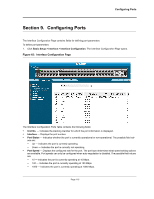
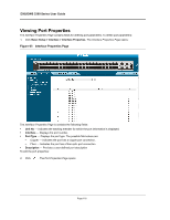
DXS/DWS 3200 Series User Guide - 10000 - Indicates the port is currently operating at 10000 Mbps. • Duplex Mode - Displays the port duplex mode. This field is configurable only when auto negotiation is dis- abled, and the port speed is set to 10M or 100M. This field cannot be configured on LAGs. The possible field values are: - Full - The interface supports transmission between the device and its link partner in both directions simultaneously. - Half - The interface supports transmission between the device and the client in only one direction at a time. • Auto Negotiation - Displays the auto negotiation status on the port. Auto negotiation is a protocol between two link partners that enables a port to advertise its transmission rate, duplex mode, and flow control abilities to its partner. • Advertisement - Defines the auto negotiation setting the port advertises. The possible field values are: - Max Capability - Indicates that all port speeds and duplex mode settings are accepted. - 10 Half - Indicates that the port advertises for a 10 Mbps speed port and half duplex mode setting. - 10 Full - Indicates that the port advertises for a 10 Mbps speed port and full duplex mode setting. - 100 Half - Indicates that the port advertises for a 100 Mbps speed port and half duplex mode setting. - 100 Full - Indicates that the port advertises for a 100 Mbps speed port and full duplex mode setting. - 1000 Full - Indicates that the port advertises for a 1000 Mbps speed port and full duplex mode setting. • Back Pressure - Displays the back pressure mode on the Port. Back pressure mode is used with half duplex mode to disable ports from receiving messages. • Flow Control - Displays the flow control status on the port. Operates when the port is in full duplex mode. • MDI/MDIX - Displays the MDI/MDIX status on the port. Hubs and switches are deliberately wired opposite the way end stations are wired, so that when a hub or switch is connected to an end station, a straight through Ethernet cable can be used, and the pairs are matched up properly. When two hubs or switches are connected to each other, or two end stations are connected to each other, a crossover cable is used to ensure that the correct pairs are connected. The possible field values are: - Auto - Use to automatically detect the cable type. - MDI (Media Dependent Interface) - Use for end stations. - MDIX (Media Dependent Interface with Crossover) - Use for hubs and switches. • LAG - Indicates whether the port is part of a Link Aggregation Group (LAG). The Interface Configuration LAG table contains the following fields: • PVE - Displays the PVE group to which the port is configured. 2. Click . The Port or LAG Interface Settings Page opens: Note In addition to the fields in the Interface Configuration Page, the Port or LAG Configuration Settings Page includes the Reactivate Suspended Port or Reactivate Suspended Lag fields. Select Reactivate Suspended Port or Reactivate Suspended Lag fields to return a suspended port or LAG to active status. Figure 66: Port Configuration Settings Page Page 116
-
 1
1 -
2
-
3
-
4
-
5
-
6
-
7
-
8
-
9
-
10
-
11
-
12
-
13
-
14
-
15
-
16
-
17
-
18
-
19
-
20
-
21
-
22
-
23
-
24
-
25
-
26
-
27
-
28
-
29
-
30
-
31
-
32
-
33
-
34
-
35
-
36
-
37
-
38
-
39
-
40
-
41
-
42
-
43
-
44
-
45
-
46
-
47
-
48
-
49
-
50
-
51
-
52
-
53
-
54
-
55
-
56
-
57
-
58
-
59
-
60
-
61
-
62
-
63
-
64
-
65
-
66
-
67
-
68
-
69
-
70
-
71
-
72
-
73
-
74
-
75
-
76
-
77
-
78
-
79
-
80
-
81
-
82
-
83
-
84
-
85
-
86
-
87
-
88
-
89
-
90
-
91
-
92
-
93
-
94
-
95
-
96
-
97
-
98
-
99
-
100
-
101
-
102
-
103
-
104
-
105
-
106
-
107
-
108
-
109
-
110
-
111
-
 112
112 -
 113
113 -
 114
114 -
 115
115 -
 116
116 -
 117
117 -
 118
118 -
 119
119 -
 120
120 -
 121
121 -
 122
122 -
123
-
124
-
125
-
126
-
127
-
128
-
129
-
130
-
131
-
132
-
133
-
134
-
135
-
136
-
137
-
138
-
139
-
140
-
141
-
142
-
143
-
144
-
145
-
146
-
147
-
148
-
149
-
150
-
151
-
152
-
153
-
154
-
155
-
156
-
157
-
158
-
159
-
160
-
161
-
162
-
163
-
164
-
165
-
166
-
167
-
168
-
169
-
170
-
171
-
172
-
173
-
174
-
175
-
176
-
177
-
178
-
179
-
180
-
181
-
182
-
183
-
184
-
185
-
186
-
187
-
188
-
189
-
190
-
191
-
192
-
193
-
194
-
195
-
196
-
197
-
198
-
199
-
200
-
201
-
202
-
203
-
204
-
205
-
206
-
207
-
208
-
209
-
210
-
211
-
212
-
213
-
214
-
215
-
216
-
217
-
218
-
219
-
220
-
221
-
222
-
223
-
224
-
225
-
226
-
227
-
228
-
229
-
230
-
231
-
232
-
233
-
234
-
235
-
236
-
237
-
238
-
239
-
240
-
241
-
242
-
243
-
244
-
245
-
246
-
247
-
248
-
249
-
250
-
251
-
252
-
253
-
254
-
255
-
256
-
257
-
258
-
259
-
260
-
261
-
262
-
263
-
264
-
265
-
266
-
267
-
268
-
269
-
270
-
271
-
272
-
273
-
274
-
275
-
276
-
277
-
278
-
279
-
280
-
281
-
282
-
283
-
284
-
285
-
286
-
287
-
288
-
289
-
290
-
291
-
292
-
293
-
294
-
295
-
296
-
297
-
298
-
299
-
300
-
301
-
302
-
303
-
304
-
305
-
306
-
307
-
308
-
309
-
310
-
311
-
312
-
313
-
314
-
315
-
316
-
317
-
318
-
319
-
320
-
321
-
322
-
323
-
324
-
325
-
326
-
327
-
328
-
329
-
330
-
331
-
332
-
333
-
334
-
335
-
336
-
337
-
338
-
339
-
340
-
341
-
342
-
343
-
344
-
345
-
346
-
347
-
348
-
349
-
350
-
351
-
352
-
353
-
354
-
355
-
356
-
357
-
358
-
359
-
360
-
361
-
362
-
363
-
364
-
365
-
366
-
367
-
368
-
369
-
370
-
371
-
372
 |
 |