Dell Alienware Area-51 Threadripper Edition R7 Service Manual - Page 84
Removing the processor liquid-cooling assembly, Prerequisites, Procedure
 |
View all Dell Alienware Area-51 Threadripper Edition R7 manuals
Add to My Manuals
Save this manual to your list of manuals |
Page 84 highlights
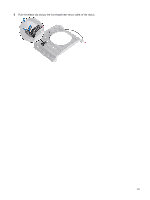
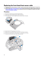
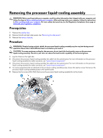
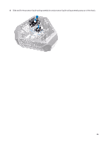
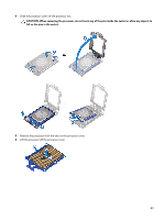
Removing the processor liquid-cooling assembly WARNING: Before working inside your computer, read the safety information that shipped with your computer and follow the steps in Before working inside your computer. After working inside your computer, follow the instructions in After working inside your computer. For more safety best practices, see the Regulatory Compliance home page at www.dell.com/regulatory_compliance. Prerequisites 1 Remove the stability foot. 2 Remove the left and right side-panels. See "Removing the side panels". 3 Remove the memory modules. Procedure WARNING: Despite having a plastic shield, the processor liquid-cooling assembly may be very hot during normal operation. Ensure that it had sufficient time to cool before you touch it. CAUTION: To ensure maximum cooling for the processor, do not touch the heat transfer areas on the processor liquid-cooling assembly. The oils in your skin can reduce the heat transfer capability of the thermal grease. 1 Lay the chassis on the right side. 2 Disconnect the processor liquid-cooling assembly fan cable from the system board. For more information on the processor liquid-cooling assembly fan cable connector, see "system-board components". 3 Disconnect the processor liquid-cooling assembly fan cable from the system board. For more information on the processor liquid-cooling assembly fan cable connector, see "system-board components". 4 In reverse sequential order as indicated on the processor cooling-assembly pump, loosen the captive screws that secure the processor liquid-cooling assembly pump to the system board. 5 Remove the four screws (#6-32x6) that secure the processor liquid-cooling assembly fan to the chassis. 84
-
 1
1 -
2
-
3
-
4
-
5
-
6
-
7
-
8
-
9
-
10
-
11
-
12
-
13
-
14
-
15
-
16
-
17
-
18
-
19
-
20
-
21
-
22
-
23
-
24
-
25
-
26
-
27
-
28
-
29
-
30
-
31
-
32
-
33
-
34
-
35
-
36
-
37
-
38
-
39
-
40
-
41
-
42
-
43
-
44
-
45
-
46
-
47
-
48
-
49
-
50
-
51
-
52
-
53
-
54
-
55
-
56
-
57
-
58
-
59
-
60
-
61
-
62
-
63
-
64
-
65
-
66
-
67
-
68
-
69
-
70
-
71
-
72
-
73
-
74
-
75
-
76
-
77
-
78
-
 79
79 -
 80
80 -
 81
81 -
 82
82 -
 83
83 -
 84
84 -
 85
85 -
 86
86 -
 87
87 -
 88
88 -
 89
89 -
90
-
91
-
92
-
93
-
94
-
95
-
96
-
97
-
98
-
99
-
100
-
101
-
102
-
103
-
104
-
105
-
106
-
107
-
108
-
109
-
110
-
111
-
112
-
113
-
114
-
115
-
116
-
117
-
118
-
119
-
120
-
121
-
122
-
123
-
124
-
125
-
126
-
127
-
128
-
129
-
130
-
131
-
132
-
133
-
134
-
135
-
136
-
137
-
138
-
139
-
140
 |
 |
