Dell Inspiron 530 Owner's Manual - Page 123
Memory
 |
UPC - 883685981020
View all Dell Inspiron 530 manuals
Add to My Manuals
Save this manual to your list of manuals |
Page 123 highlights
Pin Number 1 2 3 4 Signal Name +5 VDC GND GND +12 VDC 22-AWG Wire Red Black Black Yellow DC Power Connector P8 (For 350 W PSU only) NOTE: The P8 connector is not used on your computer. 456 123 Pin Number 1 2 3 4 5 6 Signal Name +12 VDC +12 VDC +12 VDC GND GND GND 18-AWG Wire Color Yellow Yellow Yellow Black Black Black Memory You can increase your computer memory by installing memory modules on the system board. Your computer supports DDR2 memory. For additional information on the type of memory supported by your computer, see "Memory" on page 179. NOTICE: Do not install ECC or buffered memory modules. Only unbuffered, non-ECC memory is supported. Removing and Installing Parts 123
-
 1
1 -
2
-
3
-
4
-
5
-
6
-
7
-
8
-
9
-
10
-
11
-
12
-
13
-
14
-
15
-
16
-
17
-
18
-
19
-
20
-
21
-
22
-
23
-
24
-
25
-
26
-
27
-
28
-
29
-
30
-
31
-
32
-
33
-
34
-
35
-
36
-
37
-
38
-
39
-
40
-
41
-
42
-
43
-
44
-
45
-
46
-
47
-
48
-
49
-
50
-
51
-
52
-
53
-
54
-
55
-
56
-
57
-
58
-
59
-
60
-
61
-
62
-
63
-
64
-
65
-
66
-
67
-
68
-
69
-
70
-
71
-
72
-
73
-
74
-
75
-
76
-
77
-
78
-
79
-
80
-
81
-
82
-
83
-
84
-
85
-
86
-
87
-
88
-
89
-
90
-
91
-
92
-
93
-
94
-
95
-
96
-
97
-
98
-
99
-
100
-
101
-
102
-
103
-
104
-
105
-
106
-
107
-
108
-
109
-
110
-
111
-
112
-
113
-
114
-
115
-
116
-
117
-
 118
118 -
 119
119 -
 120
120 -
 121
121 -
 122
122 -
 123
123 -
 124
124 -
 125
125 -
 126
126 -
 127
127 -
 128
128 -
129
-
130
-
131
-
132
-
133
-
134
-
135
-
136
-
137
-
138
-
139
-
140
-
141
-
142
-
143
-
144
-
145
-
146
-
147
-
148
-
149
-
150
-
151
-
152
-
153
-
154
-
155
-
156
-
157
-
158
-
159
-
160
-
161
-
162
-
163
-
164
-
165
-
166
-
167
-
168
-
169
-
170
-
171
-
172
-
173
-
174
-
175
-
176
-
177
-
178
-
179
-
180
-
181
-
182
-
183
-
184
-
185
-
186
-
187
-
188
-
189
-
190
-
191
-
192
-
193
-
194
-
195
-
196
-
197
-
198
-
199
-
200
-
201
-
202
-
203
-
204
-
205
-
206
-
207
-
208
-
209
-
210
-
211
-
212
-
213
-
214
-
215
-
216
-
217
-
218
-
219
-
220
-
221
-
222
-
223
-
224
-
225
-
226
 |
 |

Removing and Installing Parts
123
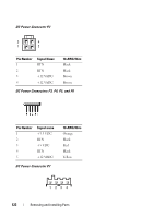
DC Power Connector P8 (For 350 W PSU only)
NOTE:
The P8 connector is not used on your computer.
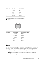
Memory
You can increase your computer memory by installing memory modules on
the system board. Your computer supports DDR2 memory. For additional
information on the type of memory supported by your computer, see
"Memory" on page 179.
NOTICE:
Do not install ECC or buffered memory modules. Only unbuffered,
non-ECC memory is supported.
Pin Number
Signal Name
22-AWG Wire
1
+5 VDC
Red
2
GND
Black
3
GND
Black
4
+12 VDC
Yellow
Pin Number
Signal Name
18-AWG Wire Color
1
+12 VDC
Yellow
2
+12 VDC
Yellow
3
+12 VDC
Yellow
4
GND
Black
5
GND
Black
6
GND
Black
1
2
3
4
6
5