Dell Inspiron 530 Owner's Manual - Page 20
CAUTION, appropriate connector. See Back Panel Connectors - power supply
 |
UPC - 883685981020
View all Dell Inspiron 530 manuals
Add to My Manuals
Save this manual to your list of manuals |
Page 20 highlights
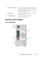
1 power connector 2 voltage selector switch 3 power supply light 4 back panel connectors 5 card slots 6 padlock rings 7 security cable slot Insert the power cable. For selecting voltage rating. Indicates power availability for power supply. Plug USB, audio, and other devices into the appropriate connector. See "Back Panel Connectors" on page 22for more information. Access connectors for any installed PCI and PCI Express cards. Padlock rings are for attaching a commercially available theft-deterrent device. The padlock rings allow you to secure the computer cover to the chassis with a padlock to prevent unauthorized access to the inside of the computer. To use the padlock rings, insert a commercially available padlock through the rings, and then lock the padlock. Security cable slot lets you attach a commercially available antitheft device to the computer. For more information, see the instructions included with the device. CAUTION: Ensure that none of the system air vents are blocked. Blocking them can cause serious thermal problems. 20 Setting Up and Using Your Computer
-
 1
1 -
2
-
3
-
4
-
5
-
6
-
7
-
8
-
9
-
10
-
11
-
12
-
13
-
14
-
 15
15 -
 16
16 -
 17
17 -
 18
18 -
 19
19 -
 20
20 -
 21
21 -
 22
22 -
 23
23 -
 24
24 -
 25
25 -
26
-
27
-
28
-
29
-
30
-
31
-
32
-
33
-
34
-
35
-
36
-
37
-
38
-
39
-
40
-
41
-
42
-
43
-
44
-
45
-
46
-
47
-
48
-
49
-
50
-
51
-
52
-
53
-
54
-
55
-
56
-
57
-
58
-
59
-
60
-
61
-
62
-
63
-
64
-
65
-
66
-
67
-
68
-
69
-
70
-
71
-
72
-
73
-
74
-
75
-
76
-
77
-
78
-
79
-
80
-
81
-
82
-
83
-
84
-
85
-
86
-
87
-
88
-
89
-
90
-
91
-
92
-
93
-
94
-
95
-
96
-
97
-
98
-
99
-
100
-
101
-
102
-
103
-
104
-
105
-
106
-
107
-
108
-
109
-
110
-
111
-
112
-
113
-
114
-
115
-
116
-
117
-
118
-
119
-
120
-
121
-
122
-
123
-
124
-
125
-
126
-
127
-
128
-
129
-
130
-
131
-
132
-
133
-
134
-
135
-
136
-
137
-
138
-
139
-
140
-
141
-
142
-
143
-
144
-
145
-
146
-
147
-
148
-
149
-
150
-
151
-
152
-
153
-
154
-
155
-
156
-
157
-
158
-
159
-
160
-
161
-
162
-
163
-
164
-
165
-
166
-
167
-
168
-
169
-
170
-
171
-
172
-
173
-
174
-
175
-
176
-
177
-
178
-
179
-
180
-
181
-
182
-
183
-
184
-
185
-
186
-
187
-
188
-
189
-
190
-
191
-
192
-
193
-
194
-
195
-
196
-
197
-
198
-
199
-
200
-
201
-
202
-
203
-
204
-
205
-
206
-
207
-
208
-
209
-
210
-
211
-
212
-
213
-
214
-
215
-
216
-
217
-
218
-
219
-
220
-
221
-
222
-
223
-
224
-
225
-
226
 |
 |
