Dell Inspiron 530 Owner's Manual - Page 165
Installing the I/O Panel, Processor Fan - replacement heatsink
 |
UPC - 883685981020
View all Dell Inspiron 530 manuals
Add to My Manuals
Save this manual to your list of manuals |
Page 165 highlights
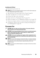
Installing the I/O Panel 1 Place the I/O panel into the slot. NOTICE: Take care not to damage the cable connectors and the cable routing clips when sliding the I/O panel into the computer. 2 Align and slide the I/O panel clamp into the I/O panel clamp slot. 3 Replace and tighten the screw that secures the I/O panel. 4 Reconnect the cables to the system board. 5 Replace the bezel (see "Replacing the Bezel" on page 137). 6 Replace the computer cover (see "Replacing the Computer Cover" on page 176). 7 Connect your computer and devices to an electrical outlet, and turn them on. 8 Verify that the computer works correctly by running the Dell Diagnostics (see "Dell Diagnostics" on page 90). Processor Fan CAUTION: Before you begin any of the procedures in this section, follow the safety instructions in the Product Information Guide. CAUTION: To guard against likelihood of electric shock, laceration by moving fan blades or other unexpected injuries, always unplug your computer from the electrical outlet before opening the cover. CAUTION: The heat sink assembly, power supply, and other components may be very hot during normal operation. Be sure that they have had sufficient time to cool before you touch them. NOTICE: To prevent static damage to components inside your computer, discharge static electricity from your body before you touch any of your computer's electronic components. You can do so by touching an unpainted metal surface on the computer chassis. NOTE: The processor fan with the heatsink is one single unit. Do not try to remove the fan separately. Removing and Installing Parts 165
-
 1
1 -
2
-
3
-
4
-
5
-
6
-
7
-
8
-
9
-
10
-
11
-
12
-
13
-
14
-
15
-
16
-
17
-
18
-
19
-
20
-
21
-
22
-
23
-
24
-
25
-
26
-
27
-
28
-
29
-
30
-
31
-
32
-
33
-
34
-
35
-
36
-
37
-
38
-
39
-
40
-
41
-
42
-
43
-
44
-
45
-
46
-
47
-
48
-
49
-
50
-
51
-
52
-
53
-
54
-
55
-
56
-
57
-
58
-
59
-
60
-
61
-
62
-
63
-
64
-
65
-
66
-
67
-
68
-
69
-
70
-
71
-
72
-
73
-
74
-
75
-
76
-
77
-
78
-
79
-
80
-
81
-
82
-
83
-
84
-
85
-
86
-
87
-
88
-
89
-
90
-
91
-
92
-
93
-
94
-
95
-
96
-
97
-
98
-
99
-
100
-
101
-
102
-
103
-
104
-
105
-
106
-
107
-
108
-
109
-
110
-
111
-
112
-
113
-
114
-
115
-
116
-
117
-
118
-
119
-
120
-
121
-
122
-
123
-
124
-
125
-
126
-
127
-
128
-
129
-
130
-
131
-
132
-
133
-
134
-
135
-
136
-
137
-
138
-
139
-
140
-
141
-
142
-
143
-
144
-
145
-
146
-
147
-
148
-
149
-
150
-
151
-
152
-
153
-
154
-
155
-
156
-
157
-
158
-
159
-
 160
160 -
 161
161 -
 162
162 -
 163
163 -
 164
164 -
 165
165 -
 166
166 -
 167
167 -
 168
168 -
 169
169 -
 170
170 -
171
-
172
-
173
-
174
-
175
-
176
-
177
-
178
-
179
-
180
-
181
-
182
-
183
-
184
-
185
-
186
-
187
-
188
-
189
-
190
-
191
-
192
-
193
-
194
-
195
-
196
-
197
-
198
-
199
-
200
-
201
-
202
-
203
-
204
-
205
-
206
-
207
-
208
-
209
-
210
-
211
-
212
-
213
-
214
-
215
-
216
-
217
-
218
-
219
-
220
-
221
-
222
-
223
-
224
-
225
-
226
 |
 |
