Gateway 9315 Gateway 9315 Server User Guide
Gateway 9315 Manual
 |
View all Gateway 9315 manuals
Add to My Manuals
Save this manual to your list of manuals |
Gateway 9315 manual content summary:
- Gateway 9315 | Gateway 9315 Server User Guide - Page 1
User Guide Gateway 9315 Server - Gateway 9315 | Gateway 9315 Server User Guide - Page 2
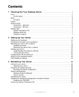
- right side 5 Connectors - left side 6 Getting Help 7 System Companion CD 7 Gateway Web site 7 Telephone support 7 2 Setting Up Your Server 9 Setting up the hardware 10 Protecting from power source problems 11 Mounting your server into a cabinet 13 Installing the bezel 18 Removing the - Gateway 9315 | Gateway 9315 Server User Guide - Page 3
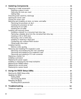
static electricity discharge 37 Opening the server case 38 Closing the server case 39 Removing and installing air ducts Filling empty drive bays 64 Installing memory 65 Memory online sparing 66 Removing and Installing PCI Troubleshooting 101 Telephone support 102 ii www.gateway.com - Gateway 9315 | Gateway 9315 Server User Guide - Page 4
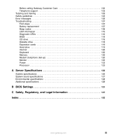
Before calling Gateway Customer Care 102 Telephone support 103 Tutoring and training 103 Safety guidelines 104 Error messages 105 Troubleshooting 107 First steps 107 120 Keyboard 120 Memory 120 Modem (telephone dial-up 120 Monitor 122 Power 123 Processor 123 A Server Specifications 125 - Gateway 9315 | Gateway 9315 Server User Guide - Page 5
iv www.gateway.com - Gateway 9315 | Gateway 9315 Server User Guide - Page 6
Chapter 1 Checking Out Your Gateway Server ■ Locating drives, ports, jacks, and controls ■ Locating system board components ■ Available help resources 1 - Gateway 9315 | Gateway 9315 Server User Guide - Page 7
LED Power/ sleep System LED fault LED System ID button System ID LED Video port Non-maskable interrupt button (recessed) USB port Reset button 2 www.gateway.com - Gateway 9315 | Gateway 9315 Server User Guide - Page 8
Back Low-profile PCI expansion card Full-height PCI expansion card Serial number I/O panel I/O panel Power connector Power supply Keyboard port LAN jacks PS/2 mouse port RJ-45 serial port USB ports Diagnostic Video port LEDs System ID LED www.gateway.com 3 - Gateway 9315 | Gateway 9315 Server User Guide - Page 9
Interior CPU 2 socket DIMM slots CPU 1 socket Processor air duct Fan module PCI riser assembly Power supply Drive bays 4 www.gateway.com - Gateway 9315 | Gateway 9315 Server User Guide - Page 10
2 socket IDE power connector Front panel USB header SATA 1 connector OEM RMC connector Configuration jumpers Power supply connector SATA 0 connector www.gateway.com +12V CPU power connector Fan board connector Diskette connector PCI fan connectors IDE connector 100-pin floppy/front panel/ATA - Gateway 9315 | Gateway 9315 Server User Guide - Page 11
Connectors - left side Mouse (top) and Keyboard Serial port B (RJ-45) LAN 1 LAN 2 DIMM slots Video USB 1 USB 2 PCI riser card (low-profile) Diagnostic LEDs (4) PCI riser card (full-height) ID LED Battery Serial port A header Chassis intrusion header BIOS select jumper 6 www.gateway.com - Gateway 9315 | Gateway 9315 Server User Guide - Page 12
you use your server. Visit the Gateway Web site at support.gateway.com for: ■ Technical documentation and product guides ■ Technical tips and support ■ Updated hardware drivers ■ Order status ■ Frequently asked questions (FAQs) Telephone support You can access a wide range of services through your - Gateway 9315 | Gateway 9315 Server User Guide - Page 13
8 www.gateway.com - Gateway 9315 | Gateway 9315 Server User Guide - Page 14
Chapter 2 Setting Up Your Server ■ Using your server safely ■ Installing your server into a cabinet ■ Starting and turning off your server ■ Setting up your operating system 9 - Gateway 9315 | Gateway 9315 Server User Guide - Page 15
surface for your server. Allow at least 6 inches at the back of the server for cabling and air circulation. ■ Use the instructions on your server's setup poster server may cause interference. Important Keep the server boxes and packing material in case you need to ship the server. 10 www.gateway - Gateway 9315 | Gateway 9315 Server User Guide - Page 16
server. Warning High voltages can enter your server through the power cord, and the modem and network connections. Protect your server protection for your server. ■ Check the energy absorption better the protection for your server. ■ Check for line can also be a problem if your server is located near, - Gateway 9315 | Gateway 9315 Server User Guide - Page 17
from data loss during a total power failure. A UPS uses a battery to keep your server running temporarily during a power failure and lets you save your work and shut down your server. You cannot run your server for an extended period of time while using only the UPS. To buy a UPS, visit accessories - Gateway 9315 | Gateway 9315 Server User Guide - Page 18
■ Server rails (2) ■ Cabinet rails (2) ■ L brackets (2, not used for this type of installation) ■ Fastener pack (1) ■ Small screws (4, #6-32 × 3/16-inch) ■ Medium screws (8, #10-32 × ½-inch) ■ Large screws (2, #10-32 × 7/8-inch) ■ Disk guides (2) ■ Handle spacers (2) ■ Nut bars (4) www.gateway.com - Gateway 9315 | Gateway 9315 Server User Guide - Page 19
than the server shown in the example.) Locking screw hole Server rail Mounting stud Slot Locking screw hole Locking screw hole Slot 3 Align the locking screw holes in the rails with the threaded screw holes in the server, then install the two locking screws through each rail. 14 www.gateway.com - Gateway 9315 | Gateway 9315 Server User Guide - Page 20
4 Place a disk guide over the disk guide screw hole towards the back of the server. Disk guide screw hole 5 Install a small screw through the disk guide and tighten the screw. Attach the remaining disk guide on the other side of the server. Disk guide Disk guide screw www.gateway.com 15 - Gateway 9315 | Gateway 9315 Server User Guide - Page 21
step). 7 Insert the slotted foot at the back of each cabinet rail between the nut bar and the post, then tighten the screws. 16 www.gateway.com - Gateway 9315 | Gateway 9315 Server User Guide - Page 22
front cabinet posts, then secure with two screws through each server rail. - OR - Follow the instructions in "Installing the bezel" on page 18 to attach both handles and secure the server into the cabinet. Warning You must support the server while installing or removing the front screws and while - Gateway 9315 | Gateway 9315 Server User Guide - Page 23
with the holes in the front side of the server. 2 Attach the handles to the sides of the server with two mounting screws on each side. (Your server may be different than the server shown in the example.) Mounting screw Mounting screw 3 Push the server, with the handles attached, into the cabinet to - Gateway 9315 | Gateway 9315 Server User Guide - Page 24
and while sliding the server off the cabinet rails. If the server is not supported, damage to the server or injury may result. 1 Remove the screws through the handles that hold the server in the cabinet. 2 While supporting the server, slide the server out from the cabinet. www.gateway.com 19 - Gateway 9315 | Gateway 9315 Server User Guide - Page 25
devices to the server, make sure that your server and devices are turned off and the power cords are unplugged. To start the server: 1 Turn on any peripheral devices connected to the server. 2 Press the power button. Power LED Power button System fault LED Reset button 20 www.gateway.com - Gateway 9315 | Gateway 9315 Server User Guide - Page 26
-on self-test (POST) routine checks the server memory and components. If POST finds any problems, the server displays error messages. Write down any error messages that you see, then see "Error messages" on page 105 and "Beep codes" on page 108 for troubleshooting information. www.gateway.com 21 - Gateway 9315 | Gateway 9315 Server User Guide - Page 27
the operating system. You may lose data if you do not follow the correct procedure. To turn off the server: 1 See the operating system's documentation or online help for instructions on shutting down the operating system. Whenever possible, you should use the operating system's shut down procedure - Gateway 9315 | Gateway 9315 Server User Guide - Page 28
DCD signal support: 1 Follow the instructions in "Preventing static electricity discharge" on page 37. Make sure you turn off the server, then instructions in "Removing and installing the PCI riser assembly" on page 69. 6 Follow the instructions in "Closing the server case" on page 39. www.gateway - Gateway 9315 | Gateway 9315 Server User Guide - Page 29
for your specific network. If you are installing an operating system because it was not already installed by Gateway, see the appropriate installation guide for instructions. Initial hardware settings Your server comes from the manufacturer with the correct initial hardware settings to operate your - Gateway 9315 | Gateway 9315 Server User Guide - Page 30
Chapter 3 Maintaining Your Server ■ Caring for your server ■ Recording the BIOS configuration ■ Managing your server and network 25 - Gateway 9315 | Gateway 9315 Server User Guide - Page 31
devices before cleaning any components. Warning When you shut down your server, the power turns off, but some electrical current still flows through your server. To avoid possible injury from electrical shock, unplug the power cord and all other cables connected to the server. 26 www.gateway.com - Gateway 9315 | Gateway 9315 Server User Guide - Page 32
remove dust and lint trapped under the keys. If you spill liquid on the keyboard, turn off your server and turn the keyboard upside down to let the liquid drain. Let the keyboard dry completely before trying to to clean the screen. Never spray cleaner directly onto the screen. www.gateway.com 27 - Gateway 9315 | Gateway 9315 Server User Guide - Page 33
start the server and attempt to fix the problem. See your operating system's documentation or online help for instructions on server set up and working. To record your BIOS configuration: 1 Print the appendix for "BIOS Settings" on page 131. 2 Restart your server, then press F2 when the Gateway - Gateway 9315 | Gateway 9315 Server User Guide - Page 34
Server security Locking the server To lock the server: 1 Remove the bezel lock keys from the inside of the bezel, then snap on the bezel. The handles must be installed for the bezel to snap on. For instructions : 1 Restart your server, then press F2 when the Gateway logo screen appears during - Gateway 9315 | Gateway 9315 Server User Guide - Page 35
BIOS Setup utility. To remove a BIOS security password: 1 Restart your server, then press F2 when the Gateway logo screen appears during startup. The BIOS Setup utility opens. 2 Select jumpers on the system board. For instructions, see "Resetting BIOS passwords" on page 98. 30 www.gateway.com - Gateway 9315 | Gateway 9315 Server User Guide - Page 36
turned on by using the Gateway Systems Manager software. To turn on the System ID LEDs: 1 Press the System ID button. The two blue System ID LEDs turn on. System ID LED System ID button System ID LED For the System ID LEDs to turn on, the server does not need to - Gateway 9315 | Gateway 9315 Server User Guide - Page 37
the instructions included with the update file. Updating the FRU/SDR The FRU/SDR must be updated whenever you add additional hardware to your server that must be monitored by the BMC or whenever you update the BIOS. Each time you update the FRU/SDR, we recommend that you check support.gateway.com - Gateway 9315 | Gateway 9315 Server User Guide - Page 38
hardware. For example, additional memory. 5 Exit the utility, remove the System Companion CD, then reboot your server. Using your System Companion CD You can use your System Companion CD to: ■ Install hardware drivers ■ Install programs ■ View server documentation Instructions for using the CD are - Gateway 9315 | Gateway 9315 Server User Guide - Page 39
34 www.gateway.com - Gateway 9315 | Gateway 9315 Server User Guide - Page 40
Chapter 4 Installing Components ■ Opening and closing the server case ■ Installing and replacing major server components 35 - Gateway 9315 | Gateway 9315 Server User Guide - Page 41
case to install components. If you are not comfortable with these procedures, get help from a computer service technician or contact Gateway Customer Care. Selecting a place to work Work on your server in an area that: ■ Is clean (avoid dusty areas) ■ Is a low-static environment (avoid carpeted - Gateway 9315 | Gateway 9315 Server User Guide - Page 42
■ Avoid static-causing surfaces such as carpeted floors, plastic, and packing foam. ■ Avoid working on the server when your work area is extremely humid. ■ Remove components from their antistatic bags only when you are ready slide expansion cards or components over any surface. www.gateway.com 37 - Gateway 9315 | Gateway 9315 Server User Guide - Page 43
installed, unlock it, then pull it off. 3 If the server is mounted in a cabinet, remove the server from the cabinet. For instructions, see "Removing the server from a cabinet" on page 19. Warning Screws are required to support the front of the server when using the standard cabinet rails. You must - Gateway 9315 | Gateway 9315 Server User Guide - Page 44
server about 1/2 inch. Panel release button 7 Lift the top panel away from the server. Closing the server case Caution Whenever you add or remove components from your server baffles and ducts, and incorrect airflow within the server. To close the server case: 1 Make sure that all of the - Gateway 9315 | Gateway 9315 Server User Guide - Page 45
3 Slide the top panel toward the front of the server until it clicks into place. 4 Replace the shipping screw (if required). 5 Replace the bezel (if required). 6 Reconnect the power cord and all other cables. 40 www.gateway.com - Gateway 9315 | Gateway 9315 Server User Guide - Page 46
server operate your server with the memory in your system or if you need to replace the system board. To remove the processor air duct: 1 Follow the instructions server, then unplug the power cord and all other cables connected to the server. 2 Follow the instructions in "Opening the server - Gateway 9315 | Gateway 9315 Server User Guide - Page 47
the air baffle: 1 Follow the instructions in "Preventing static electricity discharge" on page 37. Make sure you turn off the server, then unplug the power cord and all other cables connected to the server. 2 Follow the instructions in "Opening the server case" on page 38. 42 www.gateway.com - Gateway 9315 | Gateway 9315 Server User Guide - Page 48
Important Take note of the cable routing under and around the air baffle. You will need to re-route these cables when the baffle is reinstalled. 3 Pull up on the air baffle to remove it from the server chassis. www.gateway.com 43 - Gateway 9315 | Gateway 9315 Server User Guide - Page 49
extends from the front of the baffle under the drive bay area. 3 Line up the guide pins on the baffle with the matching holes in the chassis and in the backplane. 4 Push and incorrect airflow in the server. 5 Follow the instructions in "Closing the server case" on page 39. 44 www.gateway.com - Gateway 9315 | Gateway 9315 Server User Guide - Page 50
(but not installed in the server). As you prepare to install a diskette drive into your server, you must install the diskette server. To install a diskette drive in a converted hard drive bay: 1 Follow the instructions unplugged. 2 Follow the instructions in "Opening the server case" on page 38 - Gateway 9315 | Gateway 9315 Server User Guide - Page 51
holes in the carrier and attach the drive to the carrier with the two screws that came with the diskette drive conversion kit. 46 www.gateway.com - Gateway 9315 | Gateway 9315 Server User Guide - Page 52
the connector cover to lock it into place. 11 Insert the new drive assembly into the hard drive bay until it clicks into place. www.gateway.com 47 - Gateway 9315 | Gateway 9315 Server User Guide - Page 53
lock the cable into place. 14 Reinstall the bezel, if required, by snapping it into place on the front of the chassis. 15 Follow the instructions in "Closing the server case" on page 39. 16 Reconnect all power cords and peripheral device cables, then turn on the - Gateway 9315 | Gateway 9315 Server User Guide - Page 54
instructions in "Preventing static electricity discharge" on page 37. Make sure that you turn off the server the instructions in "Opening the server case the server. the instructions in "Installing Follow the instructions in "Installing instructions in "Closing the server case" on page 39. 12 - Gateway 9315 | Gateway 9315 Server User Guide - Page 55
hot-swappable. Before installing or removing the drive, make sure that power is turned off and the power cord is unplugged. 2 Follow the instructions in "Opening the server case" on page 38. 3 Unlock the bezel (if necessary) and remove it by pulling it from the chassis. 4 Remove the slim-line drive - Gateway 9315 | Gateway 9315 Server User Guide - Page 56
drive, then attach the board to the drive with two screws (included with your server). 7 Attach the 44-pin CD drive cable to the back of the interposer board the front of the chassis. 11 Follow the instructions in "Closing the server case" on page 39. 12 Reconnect all power cords and peripheral device cables - Gateway 9315 | Gateway 9315 Server User Guide - Page 57
instructions in "Preventing static electricity discharge" on page 37. Make sure that you turn off the server, then unplug the power cord and all other cables connected to the server instructions in "Opening the server server instructions instructions in "Closing the server case" on page 39. 13 - Gateway 9315 | Gateway 9315 Server User Guide - Page 58
to add or replace hard drives in a drive bay. Your server supports as many as three 1-inch high 3.5-inch (fixed or hot-swap) SATA hard drives. You can purchase additional drives through your Gateway Sales representative. Important Gateway tests and verifies the operation and compatibility of the - Gateway 9315 | Gateway 9315 Server User Guide - Page 59
drive to the carrier using the four screws removed from the carrier. 8 Insert the drive into the bay until it clicks into place. 54 www.gateway.com - Gateway 9315 | Gateway 9315 Server User Guide - Page 60
, with the right-angle end of the SATA data cable connected to the server board or add-in card SATA connector. See your server board documentation or add-in card documentation for assistance in locating the SATA connectors " on page 42 and "Installing the air baffle" on page 44. www.gateway.com 55 - Gateway 9315 | Gateway 9315 Server User Guide - Page 61
11 Connect the loose end of the data cable to the rear of the SATA drive. Air baffle tab Air baffle back cutout Air baffle cutout Air baffle 56 www.gateway.com - Gateway 9315 | Gateway 9315 Server User Guide - Page 62
rear of the SATA drive. 13 Reinstall the bezel, if required, by snapping it into place on the front of the chassis. 14 Follow the instructions in "Closing the server case" on page 39. 15 Reconnect all power cords and peripheral device cables, then turn on the - Gateway 9315 | Gateway 9315 Server User Guide - Page 63
drive Use these instructions only if you turn off the server, then unplug the power cord and all other cables connected to the server. 2 Follow the instructions in "Opening the server case" on the chassis. 11 Follow the instructions in "Closing the server case" on page 39. 12 Reconnect all power cords and - Gateway 9315 | Gateway 9315 Server User Guide - Page 64
and utilities installed on the server to stop all activity on the failed drive. Instructions for using the software are server. 4 If you are replacing a hard drive, remove the four screws that secure the old hard drive to the drive tray, then remove the drive from the tray. - OR - www.gateway - Gateway 9315 | Gateway 9315 Server User Guide - Page 65
the drive assembly into the drive bay. 8 Reinstall the bezel, if required, by snapping it into place on the front of the chassis. 60 www.gateway.com - Gateway 9315 | Gateway 9315 Server User Guide - Page 66
your onboard RAID solution Your server comes equipped with an onboard, chipset SATA RAID solution, which supports RAID levels 0 (striping) To launch the SATA RAID BIOS console: 1 Restart your server. 2 Press F2 when the Gateway logo screen appears during startup. The BIOS Setup utility opens - Gateway 9315 | Gateway 9315 Server User Guide - Page 67
RAID, you will see the following error message: Error (0146): Insufficient Memory to Shadow PCI ROM. This error message can be ignored. 10 Configure the RAID options, then exit the RAID BIOS console. 11 Reboot the server. To configure the SATA RAID solution: 1 Open the BIOS Setup utility gateway.com - Gateway 9315 | Gateway 9315 Server User Guide - Page 68
process. 16 When the initialization process is complete, press ESC to return to the previous menu. 17 Exit the RAID Configuration utility and reboot the server. www.gateway.com 63 - Gateway 9315 | Gateway 9315 Server User Guide - Page 69
bays Empty drive bays in the server must be filled by filler panels, empty drive carriers, or empty drive trays, as appropriate. With the bezel removed, install the appropriate carrier or filler panel, then replace the bezel by snapping it into place on the front of the server. 64 www.gateway.com - Gateway 9315 | Gateway 9315 Server User Guide - Page 70
mixed on the server board, but when mixing DIMM types, DDR333 memory will be treated as DDR266 * When using Dual Rank (double row) DIMMs, a maximum of four loads per memory channel is supported, therefore a maximum of four dual rank DIMMs can be populated on this system board. www.gateway.com 65 - Gateway 9315 | Gateway 9315 Server User Guide - Page 71
Single row Single row Empty Double row Single row Memory online sparing The chipset on the system board in the Gateway 9315 supports memory online sparing, which can provide a way to the primary DIMM is automatically removed from service. Since one DIMM per channel is always 66 www.gateway.com - Gateway 9315 | Gateway 9315 Server User Guide - Page 72
1B 4 Align the notch on the new module with the notch in the memory module slot and press the module firmly into the slot. The tabs on the sides of the memory slot should secure the memory module automatically. 5 Follow the instructions in "Closing the server case" on page 39. www.gateway.com 67 - Gateway 9315 | Gateway 9315 Server User Guide - Page 73
6 Turn on the server, then make sure that the operating system completely loads. If you receive an error, see "Memory" on page 120. 7 Follow the instructions in "Updating the FRU/SDR" on page 32. 68 www.gateway.com - Gateway 9315 | Gateway 9315 Server User Guide - Page 74
to the server. 2 Follow the instructions in "Opening the server case" on page 38. 3 If necessary, disconnect any cables that are attached to installed PCI expansion cards. 4 Lift the PCI riser assembly from the system board by lifting the two, blue latches on the assembly. www.gateway.com 69 - Gateway 9315 | Gateway 9315 Server User Guide - Page 75
of the riser assembly with the four slots in the back of the chassis. Hooks Slots 7 Press the PCI riser assembly back into the server. 8 Follow the instructions in "Closing the server case" on page 39. 9 See the card's documentation for software installation instructions. 70 www.gateway.com - Gateway 9315 | Gateway 9315 Server User Guide - Page 76
. Make sure that you turn off the server, then unplug the power cord and all other cables connected to the server. 2 Follow the instructions in "Opening the server case" on page 38. 3 If you 7 Connect any cables to the card following the instructions in the card's documentation. www.gateway.com 71 - Gateway 9315 | Gateway 9315 Server User Guide - Page 77
cord and all other cables connected to the server. 2 Follow the instructions in "Opening the server case" on page 38. 3 Remove the PCI riser assembly by following the instructions in "Removing and installing the PCI riser the contacts can cause electrostatic damage to the card. 72 www.gateway.com - Gateway 9315 | Gateway 9315 Server User Guide - Page 78
on the new PCI riser connector. 8 Press and hold the blue riser locking lever, then place the PCI riser connector onto the retention pins. www.gateway.com 73 - Gateway 9315 | Gateway 9315 Server User Guide - Page 79
the instructions in "Removing and installing a PCI expansion card" on page 71. 11 Install the PCI riser assembly by following the instructions in "Removing and installing the PCI riser assembly" on page 69. 12 Follow the instructions in "Closing the server case" on page 39. 74 www.gateway.com - Gateway 9315 | Gateway 9315 Server User Guide - Page 80
oriented correctly, then insert the replacement fan into the fan module. 7 Connect the fan power cable to the fan distribution board. 8 Follow the instructions in "Installing the processor air duct" on page 42. 9 Follow the instructions in "Closing the server case" on page 39. www.gateway.com 75 - Gateway 9315 | Gateway 9315 Server User Guide - Page 81
electricity discharge" on page 37. Make sure that you turn off the server, then unplug the power cord and all other cables connected to the server. 3 Follow the instructions in "Opening the server case" on page 38. 4 Follow the instructions in "Removing the processor air duct" on page 41. 76 www - Gateway 9315 | Gateway 9315 Server User Guide - Page 82
so could damage the processor. 6 Rotate the processor release lever a full 135° to release the processor, then lift the processor out of the socket. www.gateway.com 77 - Gateway 9315 | Gateway 9315 Server User Guide - Page 83
not remove the air dam from the processor air duct, the second processor may overheat, resulting in loss of data and possible damage to your server. 8 Before inserting the processor into the socket, make sure that: ■ The processor release lever is open all the way (135° from the closed position - Gateway 9315 | Gateway 9315 Server User Guide - Page 84
another. 12 Gradually and equally tighten each captive screw until each is firmly tightened. Do not over-tighten the screws. 13 Follow the instructions in "Installing the processor air duct" on page 42. 14 Follow the instructions in "Closing the server case" on page 39. www.gateway.com 79 - Gateway 9315 | Gateway 9315 Server User Guide - Page 85
in this server contains no user-serviceable parts. Only a qualified computer technician should service the power supply. Your server comes with turn off the server, then unplug the power cord and all other cables connected to the server. 2 Follow the instructions in "Opening the server case" on - Gateway 9315 | Gateway 9315 Server User Guide - Page 86
power supply into the chassis, then slide it towards the back of the server to engage it beneath the two retention clips at the back of the , follow the instructions in "Installing the air baffle" on page 44. 12 Follow the instructions in "Closing the server case" on page 39. www.gateway.com 81 - Gateway 9315 | Gateway 9315 Server User Guide - Page 87
the power cord and all other cables connected to the server. 2 Remove the bezel by unlocking it, then pulling it straight off the front of the chassis. 3 Follow the instructions in "Opening the server case" on page 38. 4 Follow the instructions in "Removing the air baffle" on page 42. 5 Remove all - Gateway 9315 | Gateway 9315 Server User Guide - Page 88
44. 13 Follow the instructions in "Closing the server case" on page 39. 14 Install the drives back into the server. If you are replacing the backplane, make sure that you replace the drives in the same bays you removed them from in Step 5. 15 Reinstall the bezel (if required). www.gateway.com 83 - Gateway 9315 | Gateway 9315 Server User Guide - Page 89
then follow the instructions in "Preventing static electricity discharge" on page 37. 5 Follow the instructions in "Opening the server case" on page 38. 6 Locate the old battery on the system board and note its orientation. You will need to install the new battery the same way. 84 www.gateway.com - Gateway 9315 | Gateway 9315 Server User Guide - Page 90
up, then press the new battery into the socket until it snaps into place. 9 Follow the instructions in "Closing the server case" on page 39. 10 Turn on your server, then press F2 when the Gateway logo screen appears during startup. 11 Restore any BIOS settings that you wrote down in Step 3. 12 - Gateway 9315 | Gateway 9315 Server User Guide - Page 91
turn off the server, then unplug the power cord and all other cables connected to the server. 2 Unlock the bezel, then remove it by pulling it straight off the server. 3 Follow the instructions in "Opening the server case" on page 5 Disconnect the cables from the control panel. 86 www.gateway.com - Gateway 9315 | Gateway 9315 Server User Guide - Page 92
the cables from the system board or backplane, reconnect them. 7 Slide the control panel the rest of the way into the server, until it clicks into place. 8 Follow the instructions in "Closing the server case" on page 39. 9 Replace the bezel on the front of the server. www.gateway.com 87 - Gateway 9315 | Gateway 9315 Server User Guide - Page 93
and all other cables connected to the server. 2 Follow the instructions in "Opening the server case" on page 38. 3 Follow the instructions in "Removing the processor air duct" on page 41. 4 Remove the memory modules by following the instructions in "Installing memory" on page 65. 5 Remove the PCI - Gateway 9315 | Gateway 9315 Server User Guide - Page 94
9 Slide the system board toward the front of the server. If the board is difficult to move, push on the back I/O port panel for added leverage. 10 Lift the board away line up with the threaded standoffs on the case. 12 Replace the 9 system board screws you removed in Step 8. www.gateway.com 89 - Gateway 9315 | Gateway 9315 Server User Guide - Page 95
the PCI riser assembly" on page 69. 18 Follow the instructions in "Installing the processor air duct" on page 42. 19 Follow the instructions in "Closing the server case" on page 39. 20 Turn on your server, then press F2 when the Gateway logo screen appears during startup. 21 Check BIOS settings to - Gateway 9315 | Gateway 9315 Server User Guide - Page 96
Chapter 5 Using the BIOS Setup Utility ■ Opening the BIOS Setup utility ■ Updating the BIOS ■ Resetting the BIOS settings to their factory defaults ■ Resetting the BIOS passwords 91 - Gateway 9315 | Gateway 9315 Server User Guide - Page 97
this guide's appendix for "BIOS Settings" on page 131. To open the BIOS Setup utility: 1 Restart your server, then press F2 when the Gateway logo screen your server's hardware and configuration. ■ Advanced gives you access to information and settings for PCI cards, peripheral devices, memory, and - Gateway 9315 | Gateway 9315 Server User Guide - Page 98
"BIOS Settings" on page 131. 2 Restart your server, then press F2 when the Gateway logo screen appears during startup. 3 Record any custom BIOS settings on your printout. 4 Download the BIOS update from support.gateway.com. 5 Follow the instructions in the self-extracting BIOS update file. 6 Enter - Gateway 9315 | Gateway 9315 Server User Guide - Page 99
the instructions in "Closing the server case" on page 39. Recovering the BIOS If you encounter a problem while you are updating the BIOS, such as a power outage, the BIOS update may not be successful. If the system continues to try to boot from the new, corrupted BIOS, you can manually recover - Gateway 9315 | Gateway 9315 Server User Guide - Page 100
2 Press and hold CTRL+HOME. The old BIOS is recovered. To manually recover the BIOS: 1 Turn off the server, then disconnect the power cords and all other cables connected to the server. 2 Follow the instructions in "Opening the server case" on page 44. Caution Moving the jumper while the power is - Gateway 9315 | Gateway 9315 Server User Guide - Page 101
. 9 Follow the instructions in "Opening the server case" on page 38. 10 Place the jumper back onto pins 2-3. 11 Follow the instructions in "Closing the server case" on page 39. 12 Plug in the AC power cords and turn on the server, then verify that the recovery was successful. 96 www.gateway.com - Gateway 9315 | Gateway 9315 Server User Guide - Page 102
board jumper: 1 Print the appendix for BIOS Settings in this guide. 2 Restart your server, then press F2 when the Gateway logo screen appears during startup. 3 Record any custom BIOS settings on your printout. 4 Follow the instructions in "Preventing static electricity discharge" on page 37. 5 Turn - Gateway 9315 | Gateway 9315 Server User Guide - Page 103
BIOS passwords, follow the instructions in "Resetting the BIOS" on page 97. To clear the BIOS password(s): 1 Turn off the server, then disconnect the power cords and all other cables connected to the server. 2 Follow the instructions in "Opening the server case" on page 38. 98 www.gateway.com - Gateway 9315 | Gateway 9315 Server User Guide - Page 104
the power cords and turn on the server. The BIOS password(s) is cleared. 5 Turn off the server, then disconnect the power cords and all other cables connected to the server. 6 Place the jumper back onto pins 2-3. 7 Follow the instructions in "Closing the server case" on page 39. www.gateway.com 99 - Gateway 9315 | Gateway 9315 Server User Guide - Page 105
100 www.gateway.com - Gateway 9315 | Gateway 9315 Server User Guide - Page 106
Chapter 6 Troubleshooting ■ Getting telephone support and training ■ Interpreting error messages and codes ■ Troubleshooting If the suggestions in this chapter do not correct the problem, see "Telephone support" on page 102 for more information about how to get help. 101 - Gateway 9315 | Gateway 9315 Server User Guide - Page 107
messages, and the steps you have taken. ■ Make sure that your server is nearby at the time of your call. The technician may have you follow appropriate troubleshooting steps. ■ Consider using Gateway's online technical support. Gateway's Web site has FAQs, tips, and other technical help. You can - Gateway 9315 | Gateway 9315 Server User Guide - Page 108
support Gateway offers a wide range of customer service, technical support, and information services. Telephone numbers You can access the following services through your telephone to get answers to your questions: Resource Service description NEW Gateway's fee-based software tutorial service - Gateway 9315 | Gateway 9315 Server User Guide - Page 109
to troubleshoot your server problem if: ■ The power cord or plug is damaged ■ Liquid has been spilled into your server ■ Your server was dropped ■ The case was damaged Instead, unplug your server and contact a qualified computer technician. If your server was damaged during shipment from Gateway - Gateway 9315 | Gateway 9315 Server User Guide - Page 110
an incorrect keystroke or trying to save a file to a write-protected diskette. Some messages, however, may indicate a problem that requires further troubleshooting. Diskette drive 0 seek to track 0 failed ■ Restart your server, then open the BIOS Setup utility by pressing and holding F2 while your - Gateway 9315 | Gateway 9315 Server User Guide - Page 111
, then open the BIOS Setup utility by pressing and holding F2 while your server restarts. Save the memory configuration. Missing operating system ■ The master boot record may be corrupt. For troubleshooting information, see "The master boot record is corrupted" on page 120. System Event Log Full - Gateway 9315 | Gateway 9315 Server User Guide - Page 112
the exact message before calling Gateway Customer Care. For instructions, see "Telephone support" on page 102. ■ Restart your server, then open the BIOS Setup utility by pressing and holding F2 while your server restarts. Check your configuration settings. ■ When diagnosing problems, press the non - Gateway 9315 | Gateway 9315 Server User Guide - Page 113
injury, do not attempt to troubleshoot your server problem if: ■ The power cord or plug is damaged ■ Liquid has been spilled into your server ■ Your server was dropped ■ The case was damaged Instead, unplug your server and contact a qualified computer technician or Gateway Customer Care. ■ If you - Gateway 9315 | Gateway 9315 Server User Guide - Page 114
8 9 10 11 Description Troubleshooting steps System board timer not operational. Possible system board malfunction. To eliminate the possibility of an add in-card problem, remove all expansion cards. . Same as for 4 beeps. The cache memory test failed. Same as for 4 beeps. www.gateway.com 109 - Gateway 9315 | Gateway 9315 Server User Guide - Page 115
server includes LEDs that can assist you in troubleshooting server identification Visible fault warning Front panel Identify failing memory Description Flashing = Server identification enabled ■ server chassis. These codes can provide troubleshooting information in the event of a system hang during POST. - Gateway 9315 | Gateway 9315 Server User Guide - Page 116
CMOS diagnostic byte to determine if battery power is OK and CMOS checksum is OK. Verify CMOS checksum manually by reading storage area. If the CMOS checksum is bad, update CMOS with power-on default values presence of PS/2 mouse. Detect the presence of keyboard in KBC port. www.gateway.com 111 - Gateway 9315 | Gateway 9315 Server User Guide - Page 117
ROMs. Initialize all the output devices. Allocate memory for ADM module and uncompress it. Give control memory installed in the system. Also, check for DEL or ESC keys to limit memory test. Display total memory and so on. Programming the memory hole or any kind of implementation that needs an adjustment in - Gateway 9315 | Gateway 9315 Server User Guide - Page 118
Off O Off Description Update CMOS memory size from memory found in memory test. Allocates memory for Extended BIOS Data Area from base memory. Initialize NUM-LOCK status and registers. Build ACPI tables (if ACPI is supported). Program the peripheral parameters. Enable/disable NMI gateway.com 113 - Gateway 9315 | Gateway 9315 Server User Guide - Page 119
code sets up the chipset, memory, and other components before system memory is available. The following table provides Test base 512 KB memory. Adjust policies and cache first 8 MB. Set stack D5 R O Off O Bootblock code is copied from ROM to lower system memory and control is given to - Gateway 9315 | Gateway 9315 Server User Guide - Page 120
"POST code checkpoints" on page 111 for more information. E1-E8 - - - - OEM memory detection/configuration error. This range is EC-EE reserved for chipset vendors and system manufacturers. The error and ATAPI CDROM. Disable ATAPI hardware. Jump back to checkpoint E9. www.gateway.com 115 - Gateway 9315 | Gateway 9315 Server User Guide - Page 121
updated successfully. Make flash write-disabled. Disable ATAPI hardware. Restore CPUID value back into register. Give control to F000 ROM at F000:FFF0h. 116 www.gateway.com - Gateway 9315 | Gateway 9315 Server User Guide - Page 122
. ■ Static Device Initialization (function 1) - Initializes all static devices that include manual configured onboard peripherals, memory and I/O decode windows in PCI-PCI bridges, and noncompliant PCI devices. Static 30, 40, 50 Waking from sleep state S1, S2, S3, S4, or S5. www.gateway.com 117 - Gateway 9315 | Gateway 9315 Server User Guide - Page 123
instructions, see "Replacing the CMOS battery" on page 84. CD drive Your server does not recognize a CD or the CD drive ■ Restart your server following the instructions in the manual eject hole. The drive tray opens. ■ If this problem happens frequently while the server try restarting your server. ■ To - Gateway 9315 | Gateway 9315 Server User Guide - Page 124
For instructions, see "Installing or replacing a hard drive" on page 53. ■ Reseat the drive cables on the backplane. ■ If your server has see "The master boot record is corrupted" on page 120. You are having problems with a SATA drive ■ For normal SATA drives (not SATA RAID), check gateway.com 119 - Gateway 9315 | Gateway 9315 Server User Guide - Page 125
your server and make sure that the memory modules are installed correctly. For instructions, see "Installing memory" on page 65. ■ A memory module may be defective. If possible, try another memory module and see if the error repeats. Modem (telephone dial-up) See also Internet. 120 www.gateway.com - Gateway 9315 | Gateway 9315 Server User Guide - Page 126
service. Also make sure that the modem dialing properties are set correctly. ■ If you purchased the modem from Gateway, contact Gateway Customer Care. To check the dialing properties in Windows: In Windows Server popping sounds). Line noise is a common problem that can cause the modem to connect at - Gateway 9315 | Gateway 9315 Server User Guide - Page 127
line noise, telephone service provider equipment, or support 48K uploads. The modem is not recognized by your server server. ■ Reinstall the modem device driver. For instructions, see "Using your System Companion CD" on page 33. ■ Open your server and reseat the modem. For instructions gateway.com - Gateway 9315 | Gateway 9315 Server User Guide - Page 128
monitor. For monitor troubleshooting, see "Monitor" on page 122. ■ If your server is plugged into a server from one processor to two, you may need to reconfigure your operating system so it recognizes the additional processor. For instructions, see your operating system's documentation. www.gateway - Gateway 9315 | Gateway 9315 Server User Guide - Page 129
124 www.gateway.com - Gateway 9315 | Gateway 9315 Server User Guide - Page 130
Appendix A Server Specifications The following specifications are for the standard configuration. Your server may contain optional equipment. All specifications are subject to change. 125 - Gateway 9315 | Gateway 9315 Server User Guide - Page 131
in server) Supports one full-length, full-height and one low-profile PCI expansion card 450 W Supports Windows Server 2003, Windows Small Business Server 2003, Novell Netware, and SuSE Linux. Compatible with: ■ Windows 2000 Server ■ Novell NetWare 6.5 ■ FCC Class A ■ UL ■ cUL 126 www.gateway.com - Gateway 9315 | Gateway 9315 Server User Guide - Page 132
.3u auto-negotiation support ■ Full duplex support ■ Ultra ATA/100 support (1 connector, 2 channels) ■ Up to 3 SATA fixed drives (RAID level 0 or 1 supported) ■ Up to 3 SATA hot-swap drives (optional) (RAID level 0 or 1 supported) ACPI compliance Supports: ■ S0 ■ S1 ■ S4 ■ S5 www.gateway.com 127 - Gateway 9315 | Gateway 9315 Server User Guide - Page 133
conditions. At no time should the server run under conditions which violate these 10° to 35°C); derated 0.9°F (0.5°C) for every 1,000 feet (305 meters). Use of 2 GB DIMMs derates the server to 86°F (30°C) 10,000 feet (3,048 meters) maximum Nonoperating: 90% relative (noncondensing) at 86° F - Gateway 9315 | Gateway 9315 Server User Guide - Page 134
For more information about your server, such as memory size, hard drive size, and processor type, visit Gateway's eSupport page at support.gateway.com. The eSupport page also has links to additional Gateway documentation and detailed specifications for your own server. www.gateway.com 129 - Gateway 9315 | Gateway 9315 Server User Guide - Page 135
130 www.gateway.com - Gateway 9315 | Gateway 9315 Server User Guide - Page 136
Appendix B BIOS Settings If you ever need to restore your BIOS settings, such as after a system board change, a record of the settings will make the process much easier. You can print this appendix, then record your custom BIOS settings on the printout. Only settings which can be changed are listed. - Gateway 9315 | Gateway 9315 Server User Guide - Page 137
To view all BIOS settings: 1 Restart your server 2 Press F2 when the Gateway logo screen appears during startup. The BIOS Setup utility opens. 3 Select menus and submenus to display setting information. BIOS menu Main Advanced BIOS submenu Setting - Gateway 9315 | Gateway 9315 Server User Guide - Page 138
device details/settings Selects IDE Device Configuration sub-menu with additional device details/settings Selects IDE Device Configuration submenu with additional device details/settings www.gateway.com 133 - Gateway 9315 | Gateway 9315 Server User Guide - Page 139
A Onboard Floppy Controller Disabled 720 KB 3 1/2" 1.44 MB 3 1/2" 2.44 MB 3 1.2" Disabled Enabled Serial Port A Address Disabled 3F8/IRQ4 2F8/IRQ3 3E8/IRQ4 2E8/IRQ3 www.gateway.com - Gateway 9315 | Gateway 9315 Server User Guide - Page 140
USB Devices Enabled (List of USB devices detected by BIOS) USB Function Legacy USB Support Port 60/64 Emulation USB 2.0 Controller USB 2.0 Controller Mode USB Mass Storage Device Configuration submenu with USB Device enable Disabled Enabled Enabled Disabled Disabled Enabled www.gateway.com 135 - Gateway 9315 | Gateway 9315 Server User Guide - Page 141
136 BIOS submenu Memory Configuration Setting Onboard NIC 1 ROM Onboard NIC 2 (Right) Onboard NIC 2 ROM Slot 1 Option ROM Slot 3 Option ROM Slot 4 Option ROM DIMM 1A (Information) DIMM 1B (Information) DIMM 2A (Information) DIMM 2B (Information) DIMM 3A (Information) www.gateway.com Value - Gateway 9315 | Gateway 9315 Server User Guide - Page 142
reserves memory to replace failures. Spare Disabled Boot Settings Configuration Quick Boot Quiet Boot Bootup Num-Lock PS/2 Mouse Support POST Error Pause Hit Message Display Disabled Enabled Disabled Enabled Off On Disabled Enabled Auto Disabled Enabled Disabled Enabled www.gateway.com - Gateway 9315 | Gateway 9315 Server User Guide - Page 143
(Specifies boot sequence from the available devices.) Varies (Specifies boot sequence from the available devices.) Varies (Specifies boot sequence from the available devices.) 138 www.gateway.com - Gateway 9315 | Gateway 9315 Server User Guide - Page 144
Access View Only Limited Full Access (Clears user password) Disabled Enabled Disabled Enabled 1 minute 2 minutes 5 minutes 10 minutes 20 minutes 60 minutes 120 minutes www.gateway.com 139 - Gateway 9315 | Gateway 9315 Server User Guide - Page 145
NMI Control Value [Z] [L] Disabled Enabled Disabled Enabled Disabled Enabled System Management Server Board Part Number Varies Server Board Serial Number Varies NIC 1 MAC Address Varies NIC 2 MAC Address (HSBP) Firmware revision of the Hotswap controller. N/A if not present. www.gateway.com - Gateway 9315 | Gateway 9315 Server User Guide - Page 146
Redirection Port Event Log Configuration Serial Port Connector Clear All Event Logs BIOS Event Logging Critical Event Logging ECC Event Logging PCI Error Logging www.gateway.com Value Disabled Serial A Serial B 9600 19.2K 38.4K 57.6K 115.2K No Flow Control CTS/RTS XON/XOFF CTS/RTS + CD PC - Gateway 9315 | Gateway 9315 Server User Guide - Page 147
disabled) FRB-2 Policy Disable BSP (not supported) Do not disable BSP (not supported) Retry on Next Boot Disable FRB2 Timer Late POST Timeout Disabled 5 minutes 10 minutes 15 minutes 20 minutes Hard Disk OS Boot Timeout Disabled 5 minutes 10 minutes 15 minutes 20 minutes 142 www.gateway.com - Gateway 9315 | Gateway 9315 Server User Guide - Page 148
. BIOS submenu BIOS 2nd level submenu IDE Configuration (Cont'd) Mixed P-ATA / S-ATA Setting First ATA Channel Second ATA Channel Value P-ATA M-S S-ATA M-S S-ATA M-S None www.gateway.com 143 - Gateway 9315 | Gateway 9315 Server User Guide - Page 149
) Mode Device information Device vendor Device size Device LBA mode Device block mode Device PIO mode Device Async DMA mode Device Ultra DMA mode Device S.M.A.R.T. support Not Installed Auto CDROM ARMD Disabled Auto Disabled Auto 144 www - Gateway 9315 | Gateway 9315 Server User Guide - Page 150
Delay Device #1 Value 10 Sec 20 Sec 30 Sec 40 Sec Displayed if a device is detected. Includes a DeviceID string returned by the USB device. www.gateway.com 145 - Gateway 9315 | Gateway 9315 Server User Guide - Page 151
BIOS submenu BIOS 2nd level submenu Setting Emulation Type Device #n Emulation Type Value Auto Floppy Forced FDD Hard Disk CDROM Displayed if a device is detected. Includes a DeviceID string returned by the USB device. Auto Floppy Forced FDD Hard Disk CDROM 146 www.gateway.com - Gateway 9315 | Gateway 9315 Server User Guide - Page 152
Appendix C Safety, Regulatory, and Legal Information ■ Safety information ■ Legal and Regulatory Information 147 - Gateway 9315 | Gateway 9315 Server User Guide - Page 153
instructions to help guard against personal injury and damage to your Gateway system. Setting up your system ■ Read and follow all instructions before cleaning the system. ■ Unplug the system from the wall outlet and refer servicing to qualified personnel if: ■ The power cord or plug is damaged. ■ - Gateway 9315 | Gateway 9315 Server User Guide - Page 154
Important Do not use Gateway products in areas classified as hazardous locations. Such areas include patient care areas of medical and dental facilities, oxygen-laden facilities. Warning To reduce the risk of fire, use only No. 26 AWG or larger telecommunications line cord. www.gateway.com 149 - Gateway 9315 | Gateway 9315 Server User Guide - Page 155
15 Class A Statement The server is designated as complying with in accordance with the instruction manual, may cause harmful modifications not expressly approved by Gateway could void the FCC service may be required. The telephone company may request that you disconnect the equipment until the problem - Gateway 9315 | Gateway 9315 Server User Guide - Page 156
Gateway Companies, Inc. 610 Gateway Drive, North Sioux City, SD 57049 (605) 232-2000 Fax: (605) 232-2023 Product: ■ Gateway 9315 Server For In some cases, the inside wiring associated with a single-line individual service may be extended by means of a certified connector assembly. The customer - Gateway 9315 | Gateway 9315 Server User Guide - Page 157
combination of devices subject only to the requirement that the sum of the Ringer Equivalence Numbers of all the devices does not exceed 5. 152 www.gateway.com - Gateway 9315 | Gateway 9315 Server User Guide - Page 158
(DHHS) Radiation Performance Standard. Should the unit ever need servicing, contact an authorized service location. Warning Use of controls or adjustments or performance of procedures other than those specified in this manual may result in hazardous radiation exposure. To prevent exposure to - Gateway 9315 | Gateway 9315 Server User Guide - Page 159
. No part of it may be reproduced or transmitted by any means or in any form, without prior consent in writing from Gateway. The information in this manual has been carefully checked and is believed to be accurate. However, changes are made periodically. These changes are incorporated in newer - Gateway 9315 | Gateway 9315 Server User Guide - Page 160
diagnostic LEDs 115 C cabinet removing server 19 card installing 69, 71 slot location 4, 5, 69 troubleshooting 119 case closing 39 opening 38 CD Gateway Systems Manager 29 System Companion 33 troubleshooting 118 CD drive installing 50 location 2 troubleshooting 118 checkpoints ACPI runtime 117 - Gateway 9315 | Gateway 9315 Server User Guide - Page 161
117 POST code checkpoints 111 DIM code checkpoints 117 DIMM see memory DIMM slots location 6 diskette drive connector 5, 6 installing 50 location 2 replacing 50 troubleshooting 118 display troubleshooting 122 documentation Gateway Web site 7 System Companion CD 33 drive bays location 2 drivers - Gateway 9315 | Gateway 9315 Server User Guide - Page 162
Gateway Systems Manager 29 H hard drive indicator 2 installing 53 LED indicator 2 replacing 53 troubleshooting 119 heat sink installing 76 help telephone support drive 53 heat sink 76 hot-swap backplane 82 hot-swap drive 53 memory 65 PCI expansion card 69, 71 PCI riser assembly 69 PCI riser connector - Gateway 9315 | Gateway 9315 Server User Guide - Page 163
26 cleaning case 26 cleaning keyboard 27 cleaning screen 27 Gateway Systems Manager 29 general guidelines 26 recording BIOS configuration 28 master boot record 120 memory installing 65 location 5, 6 online sparing 66 troubleshooting 120 memory slots location 4 messages 105 modem connection speed 122 - Gateway 9315 | Gateway 9315 Server User Guide - Page 164
2 source problems 11 static electricity 37 surge protectors 11 troubleshooting 123 uninterruptible screen cleaning 27 troubleshooting 122 SDRAM see memory security locking server 29 set server back 3 front 2 interior 4 starting 20 turning off 22 Server menu BIOS Setup utility 92 www.gateway.com 159 - Gateway 9315 | Gateway 9315 Server User Guide - Page 165
connection 120 keyboard 120 LED information 110 master boot record 120 memory 120 modem 120 monitor 122 power 123 power source problems 11 processor 123 safety guidelines 104 technical support 102 telephone support 102 video 122 turning off server 22 turning on server 20 160 www.gateway.com - Gateway 9315 | Gateway 9315 Server User Guide - Page 166
U uninterruptible power supply (UPS) 12 updating baseboard management controller firmware 32 BIOS 93 firmware 32 UPS 12 USB ports internal connector 5, 6 location 2, 3 user password 29 utilities BIOS Setup 91 V VGA port 2, 3 Video connectors 6 W Web site Gateway 7 www.gateway.com 161 - Gateway 9315 | Gateway 9315 Server User Guide - Page 167
162 www.gateway.com - Gateway 9315 | Gateway 9315 Server User Guide - Page 168
A MAN 9315 1U USR GDE R0 01/05
-
 1
1 -
 2
2 -
 3
3 -
 4
4 -
 5
5 -
 6
6 -
 7
7 -
8
-
9
-
10
-
11
-
12
-
13
-
14
-
15
-
16
-
17
-
18
-
19
-
20
-
21
-
22
-
23
-
24
-
25
-
26
-
27
-
28
-
29
-
30
-
31
-
32
-
33
-
34
-
35
-
36
-
37
-
38
-
39
-
40
-
41
-
42
-
43
-
44
-
45
-
46
-
47
-
48
-
49
-
50
-
51
-
52
-
53
-
54
-
55
-
56
-
57
-
58
-
59
-
60
-
61
-
62
-
63
-
64
-
65
-
66
-
67
-
68
-
69
-
70
-
71
-
72
-
73
-
74
-
75
-
76
-
77
-
78
-
79
-
80
-
81
-
82
-
83
-
84
-
85
-
86
-
87
-
88
-
89
-
90
-
91
-
92
-
93
-
94
-
95
-
96
-
97
-
98
-
99
-
100
-
101
-
102
-
103
-
104
-
105
-
106
-
107
-
108
-
109
-
110
-
111
-
112
-
113
-
114
-
115
-
116
-
117
-
118
-
119
-
120
-
121
-
122
-
123
-
124
-
125
-
126
-
127
-
128
-
129
-
130
-
131
-
132
-
133
-
134
-
135
-
136
-
137
-
138
-
139
-
140
-
141
-
142
-
143
-
144
-
145
-
146
-
147
-
148
-
149
-
150
-
151
-
152
-
153
-
154
-
155
-
156
-
157
-
158
-
159
-
160
-
161
-
162
-
163
-
164
-
165
-
166
-
167
-
168
 |
 |

User Guide
Gateway 9315 Server