GE 60-806-95R-16Z Installation Instructions - Page 10
Total System Power and Wire Length Guidelines
 |
UPC - 046188090938
View all GE 60-806-95R-16Z manuals
Add to My Manuals
Save this manual to your list of manuals |
Page 10 highlights
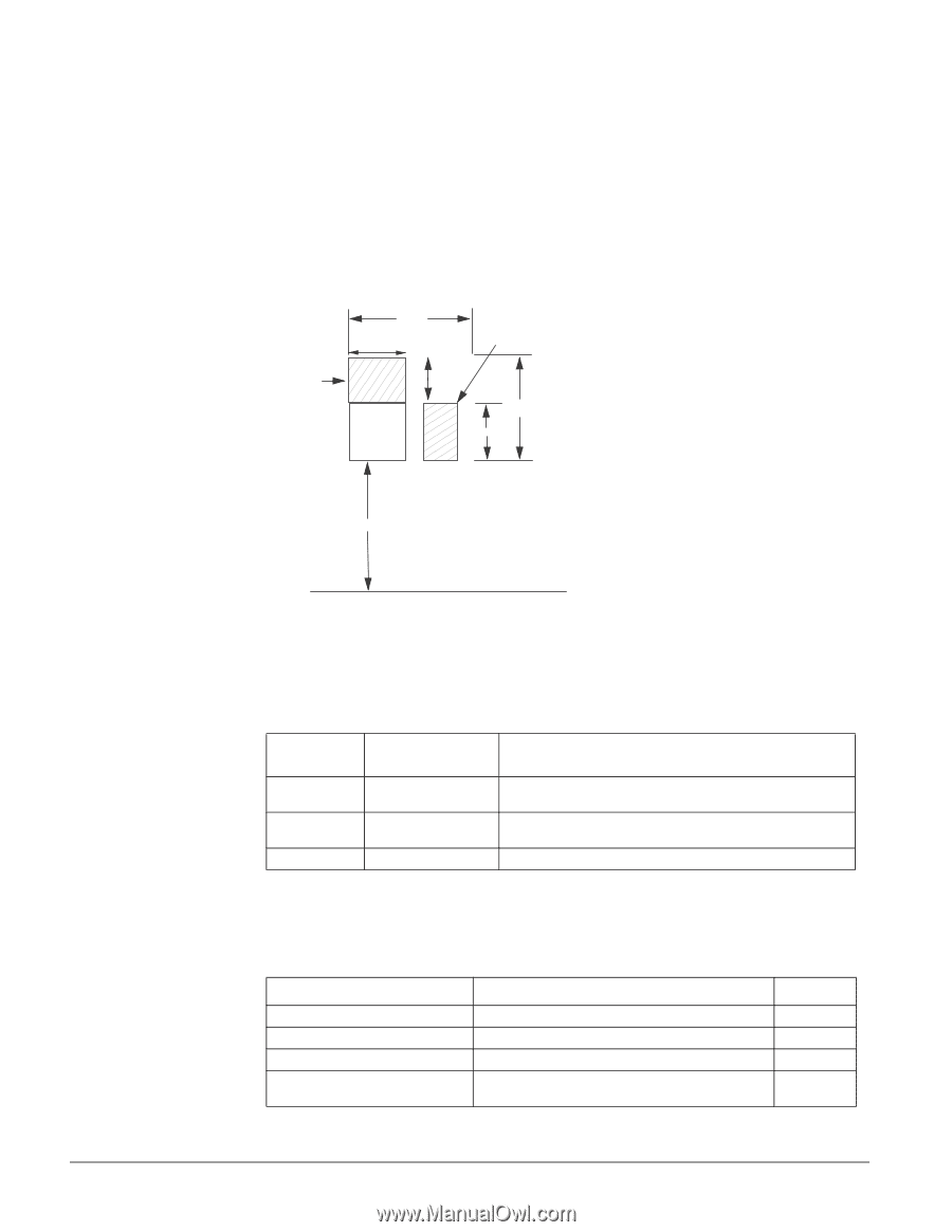
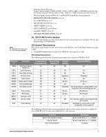
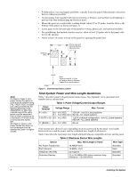
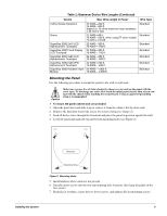
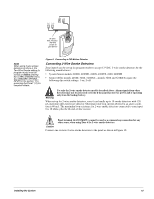
• To help reduce wire run lengths and labor, centrally locate the panel with relation to detection devices whenever possible. • Avoid running wires parallel with electrical wiring or fixtures, such as fluorescent lighting, to prevent wire runs from picking up electrical noise. • Mount the panel at a comfortable working height (about 45 to 55 inches from the floor to the bottom of the panel, as shown in Figure 1). • Leave space to the left and right of the panel for wiring, phone jack, and optional modules. • For installations that include wireless sensors, allow at least 10 inches above the panel cabinet for the antenna. • Allow at least 24 inches in front of the panel for opening the panel door. Antenna Area 1 6 .2 5 " 9" 10" Phone Jack and Optional Module Mounting Area 21" 11" Note A) Class 2, Class 3, and power-limited fire alarm circuits must be installed using FPL, FPLR, FPLP, or substitute cable permitted by the National Electrical Code ANSI/NFPA 70. Wire that extends beyond the cable jacket must be separated from all other conductors by a minimum of 1/4-inch or by a nonconductive barrier. OR (B) Class 2, Class 3, and power-limited fire alarm circuit conductors must be installed as Class 1 or higher circuits. 4 5 -5 5 " Note: Allow at Least 24' in Front of Panel to Allow for Opening Cabinet Door and Access to Floor Figure 1. Determining Panel Location Total System Power and Wire Length Guidelines Table 1 describes panel voltage/current output ranges. See Appendix A for maximum and standby device current draw. Table 1: Panel Voltage/Current Output Ranges Panel Terminal Voltage Range Max. Current 4 (+12V) 8.5 - 14.2 VDC 750 mA-non-UL Listed systems 9.1 - 14.2 VDC (UL) 90 mA-UL Listed systems 7 (OUT1/+12) 8.5 - 14.2 VDC 1.25 A at default configuration-non-UL Listed systems 650 mA-UL Listed systems 17 (Z6/2W+) 8.9 - 13.7 VDC 80 mA Total system wire allowed varies depending on devices powered by the panel, wire length between devices and the panel, and the combined wire length of all devices. Table 2 describes the maximum wire length allowed between compatible devices and the panel. Table 2: Maximum Device Wire Lengths Device Max. Wire Length to Panel Wire Type AC Power Transformer Earth Ground Telephone (RJ-31X) Detection Devices 18 AWG-25 ft. 16 AWG-25 ft. as required 22 or 18 AWG-300 ohms maximum loop resistance + 2k end-of-line Stranded Solid Stranded Stranded 5 Installing the System
-
 1
1 -
2
-
3
-
4
-
 5
5 -
 6
6 -
 7
7 -
 8
8 -
 9
9 -
 10
10 -
 11
11 -
 12
12 -
 13
13 -
 14
14 -
 15
15 -
16
-
17
-
18
-
19
-
20
-
21
-
22
-
23
-
24
-
25
-
26
-
27
-
28
-
29
-
30
-
31
-
32
-
33
-
34
-
35
-
36
-
37
-
38
-
39
-
40
-
41
-
42
-
43
-
44
-
45
-
46
-
47
-
48
-
49
-
50
-
51
-
52
-
53
-
54
-
55
-
56
-
57
-
58
-
59
-
60
-
61
-
62
-
63
-
64
-
65
-
66
-
67
-
68
-
69
-
70
-
71
-
72
-
73
-
74
-
75
-
76
 |
 |