GE 60-806-95R-16Z Installation Instructions - Page 47
Exiting Programming Mode
 |
UPC - 046188090938
View all GE 60-806-95R-16Z manuals
Add to My Manuals
Save this manual to your list of manuals |
Page 47 highlights
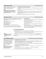
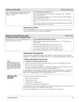
OUTPUTS-this menu lets you assign the two built-in panel outputs to partitions and set their configuration numbers. The following describes how to program the settings that appear under ONBOARD OPTIONS- INPUTS. Smoke Verify (0900) Onboard Options-Inputs (Default=off) This setting controls the number of sensor group 26 (fire) zone trips needed to report a fire alarm. • Hardwire Smokes: will determine whether or not the panel requires two alarm signals within five minutes (on) from 2-wire smoke detectors connected to panel zone input 6 and/or SnapCard zone inputs or any other hardwire zone learned into group 26 (fire) before activating system sirens and reporting to a central station (or pager). • Wireless Smokes: the first trip of a group 26 RF sensor will cause a local fire alarm. The second trip of any group 26 zone within the siren timeout will cause that fire alarm to be reported to the central station. Note RF smoke detectors repeat the alarm transmission every 60 seconds as long as they are detecting smoke. This repeated transmission will serve as the second zone trip, causing the alarm to be reported. ¾ To turn Smoke Verify off or on: 1. With the display showing ONBOARD OPTIONS, press ƒ twice. The display shows SMOKE VERIFY OFF/ON (current setting). 2. Press 1 (off) or 2 (on). The display flashes the entered number. Press ƒ and the display shows the new setting. Note For California State Fire Marshall Listed installations, this feature must be off. Two-Wire Smoke (0901) Onboard Options-Inputs (Default=off) This setting determines whether panel zone input 6 is set up for 2-wire smoke detectors (on) or for standard intrusion or 4-wire smoke detectors (off). Note If 2-wire smoke detectors are connected to hardwire zone input 6, this setting must be turned on before entering the LEARN SENSORS menu. ¾ To turn Two-Wire Smoke off or on: 1. With the display showing ONBOARD OPTIONS, press ƒ twice, then B once. The display shows TWO WIRE SMOKE OFF/ON (current setting). 2. Press 1 (off) or 2 (on). The display flashes the entered number. Press ƒ and the display shows the new setting. Output 1, 2 (09100-output 1) (09110-output 2) Onboard Options-Inputs (Defaults: Output 1=00410, Output 2=01710) This setting lets you assign the selected output a 5-digit config- ¾ To set up onboard Output 1 & 2 partition and configura- uration number that determines which system event activates tion assignments: the output and the duration or time the output is activated. 1. With the display showing ONBOARD OPTIONS, press ƒ + The first three digits represent the trigger number of an event, B. The display shows OUTPUT PROGRAMMING. such as an alarm, open sensor, or arming the system. 2. Press ƒ and the display shows OUTPUT 1. Press B to select The last two digits represent how the output responds, such as OUTPUT 2. momentary, sustained (or latched), or for a preset time. 3. After selecting the desired output, press ƒ. The display Tables A6-A10 in "Appendix A" identify system event trigger shows CONFIGURATION (current setting). and response numbers. 4. Enter the desired configuration number. The display flashes the entered number. Press ƒ and the display shows the new setting. Exiting Programming Mode After all installer/dealer programming is completed, use the following procedure to exit programming mode. ¾ To exit programming mode: 1. Press , until the display shows SYSTEM PROGRAMMING. 2. Press A once and the display shows EXIT PROGRAMMING. Programming the Panel 42
-
 1
1 -
2
-
3
-
4
-
5
-
6
-
7
-
8
-
9
-
10
-
11
-
12
-
13
-
14
-
15
-
16
-
17
-
18
-
19
-
20
-
21
-
22
-
23
-
24
-
25
-
26
-
27
-
28
-
29
-
30
-
31
-
32
-
33
-
34
-
35
-
36
-
37
-
38
-
39
-
40
-
41
-
 42
42 -
 43
43 -
 44
44 -
 45
45 -
 46
46 -
 47
47 -
 48
48 -
 49
49 -
 50
50 -
 51
51 -
 52
52 -
53
-
54
-
55
-
56
-
57
-
58
-
59
-
60
-
61
-
62
-
63
-
64
-
65
-
66
-
67
-
68
-
69
-
70
-
71
-
72
-
73
-
74
-
75
-
76
 |
 |
