GE 60-806-95R-16Z Installation Instructions - Page 53
Testing Phone Communication, Testing Central Station/ r Communication, Testing Outputs/Sirens
 |
UPC - 046188090938
View all GE 60-806-95R-16Z manuals
Add to My Manuals
Save this manual to your list of manuals |
Page 53 highlights
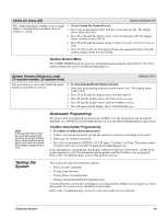
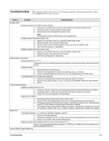
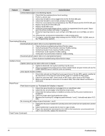
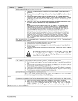
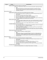
Note The way information is displayed varies with pager services and may not match the example to the right. Account numbers with alpha-characters also vary when displayed, depending on pager service. Account numbers are not displayed if Streamlining is turned on. When possible, locate wireless sensors within 100 feet of the panel. While a transmitter may have a range of 1,000 feet or more out in the open, the environment at the installation site can have a significant effect on transmitter range. Refer to the "Troubleshooting" section to resolve the problem. For wireless sensors that don't respond, use an ITI RF Sniffer (60-401) test tool to verify that the sensor is transmitting. Constant beeps from the RF Sniffer indicate a runaway (faulty) sensor. Remove the sensor battery and replace the sensor. Testing Phone Communication Perform a phone test to check the phone communication between the panel and the central monitoring station. ¾ To perform a phone test: 1. Contact the central monitoring station to inform them that you are testing the system. 2. Press 8 + system master CODE + 2. The display shows PHONE TEST and the touchpad sounds one beep. When the panel completes the test, the system returns to the previous arming level automatically. If the display continues to show PHONE TEST for 1½ minutes or more, enter 1 + system master CODE and refer to the "Troubleshooting" section. Testing Central Station/Pager Communication After performing sensor and phone tests, check that the system is reporting alarms successfully to the central station (or pager). ¾ To test communication with the central station/pager: 1. Call the central station and tell the operator that you will be testing the system. 2. Arm the system. 3. Test each of the touchpad and wireless panic buttons and trip at least one sensor of each type (fire, intrusion, etc.) to verify correct operation. 4. Check pager displays to verify reports are received. Pagers display an event code, digit sensor number, and the last four digits of the account number. For example, a pager display of 999 002 7468 indicates the following; 999 = alarm condition, 002 = sensor/zone in alarm or user number, and 7468 = last four digits of account number. Table 5 describes pager system event codes. Table 6 describes pager sensor/ zone number and user number report codes 5. When you finish testing the system, call the central monitoring station to verify that the alarms were received. Testing Outputs/Sirens All outputs (Onboard and SnapCard) should be tested to verify configuration programming. ¾ To Test Outputs: 1. Contact the central monitoring station to inform them that you are testing the system. 2. Verify that all wiring at the panel and output devices is correct. 3. Activate the appropriate device to trigger each output as programmed. 4. Verify that each output responds according to the programmed configuration number. For outputs that trigger sirens, verify that the correct alarm sounds are produced from these sirens. Table 7 describes the system alarm sounds you should hear for each alarm event. Contact the central monitoring station when you are finished testing. ! Caution Be sure to contact the central monitoring station before activating outputs that trigger from an alarm condition. Testing the System 48
-
 1
1 -
2
-
3
-
4
-
5
-
6
-
7
-
8
-
9
-
10
-
11
-
12
-
13
-
14
-
15
-
16
-
17
-
18
-
19
-
20
-
21
-
22
-
23
-
24
-
25
-
26
-
27
-
28
-
29
-
30
-
31
-
32
-
33
-
34
-
35
-
36
-
37
-
38
-
39
-
40
-
41
-
42
-
43
-
44
-
45
-
46
-
47
-
 48
48 -
 49
49 -
 50
50 -
 51
51 -
 52
52 -
 53
53 -
 54
54 -
 55
55 -
 56
56 -
 57
57 -
 58
58 -
59
-
60
-
61
-
62
-
63
-
64
-
65
-
66
-
67
-
68
-
69
-
70
-
71
-
72
-
73
-
74
-
75
-
76
 |
 |
