GE 60-806-95R-16Z Installation Instructions - Page 11
Mounting the Panel
 |
UPC - 046188090938
View all GE 60-806-95R-16Z manuals
Add to My Manuals
Save this manual to your list of manuals |
Page 11 highlights
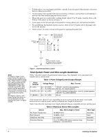
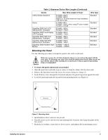
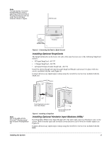
Table 2: Maximum Device Wire Lengths (Continued) Device Max. Wire Length to Panel Wire Type 2-Wire Smoke Detectors Sirens SuperBus 2000 2x16 LCD Alphanumeric Touchpad SuperBus 2000 Fixed Display LCD Touchpad SuperBus 2000 2x20 LCD Alphanumeric Touchpad SuperBus 2000 2x20 VFD Alphanumeric Touchpad SuperBus 2000 Hardwire Input Module 22 AWG-330 ft. 18 AWG-830 ft. (based on 10 ohms maximum loop resistance + 2k end-of-line) 22 AWG-80 ft. 18 AWG-200 ft. when using ITI siren models 13-469 or 13-046 22 AWG-300 ft. 18 AWG- 750 ft. 22 AWG-300 ft. 18 AWG- 750 ft. 22 AWG-250 ft. 18 AWG- 600 ft. 22 AWG-250 ft. 18 AWG- 600 ft. 22 AWG-1,800 ft. 18 AWG- 4,500 ft. Stranded Stranded Stranded Stranded Stranded Stranded Stranded Mounting the Panel Use the following procedure to mount the panel to the wall or wall studs. ! Caution Make sure you are free of static electricity whenever you work on the panel with the cover open. To discharge any static, first touch the metal panel chassis, then stay in contact with the chassis when touching the circuit board. Using an approved grounding strap is recommended. ¾ To mount the panel cabinet and circuit board: 1. Open the panel door and slide it up to remove it from the cabinet. Set the door aside. 2. Remove the knockout to provide access for system wiring (see Figure 2). 3. Feed all device wires through the knockout and place the panel in position against the wall. 4. Level the panel and mark the top and bottom mounting holes (see Figure 2). Knockout Mounting Holes Figure 2. Mounting Holes 5. Install anchors where studs are not present. 6. Partially insert screws into the two top mounting hole locations, then hang the panel on the two screws. 7. Recheck for levelness, insert the two lower screws, and tighten all four mounting screws. Installing the System 6
-
 1
1 -
2
-
3
-
4
-
5
-
 6
6 -
 7
7 -
 8
8 -
 9
9 -
 10
10 -
 11
11 -
 12
12 -
 13
13 -
 14
14 -
 15
15 -
 16
16 -
17
-
18
-
19
-
20
-
21
-
22
-
23
-
24
-
25
-
26
-
27
-
28
-
29
-
30
-
31
-
32
-
33
-
34
-
35
-
36
-
37
-
38
-
39
-
40
-
41
-
42
-
43
-
44
-
45
-
46
-
47
-
48
-
49
-
50
-
51
-
52
-
53
-
54
-
55
-
56
-
57
-
58
-
59
-
60
-
61
-
62
-
63
-
64
-
65
-
66
-
67
-
68
-
69
-
70
-
71
-
72
-
73
-
74
-
75
-
76
 |
 |
