GE 60-806-95R-16Z Installation Instructions - Page 59
Appendix A, System, Configuration, Worksheets
 |
UPC - 046188090938
View all GE 60-806-95R-16Z manuals
Add to My Manuals
Save this manual to your list of manuals |
Page 59 highlights
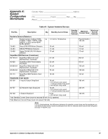
Appendix A: System Configuration Worksheets Customer Name Address City County State ___ Zip __________ Phone Table A1: System Hardwire Devices Part No. Description Qty. Standby Current Draw Standby Current Subtotal Maximum Current Draw Maximum Current Subtotal Hardwire Sensors/Detectors N/A System sensor models 2100D, na 1.2 mA for 10 detectors 2100TD, 2100S, 2100TS, 2400, 2400TH, or ESL series 429AT, 521B, 521BXT 13-463 Visus LP60 PIR Motion Detector 10 mA 13-464 DS940 PIR Motion Detector 17 mA 13-468 Optex RX-040 (PI) PIR Motion Detector 17 mA SuperBus 2000 Devices (4 maximum) 60-746-01 SuperBus 2000 2x16 LCD Alphanumeric Touchpad 57 mA 60-820 SuperBus 2000 Fixed Display Touchpad 33 mA 60-803-04 SuperBus 2000 2x20 LCD Alphanumeric Touchpad 75 mA 60-804-04 SuperBus 2000 2x20 VFD Alphanumeric Touchpad 75 mA 60-774 SuperBus 2000 Hardwire Input Module 18 mA SnapCards (1 per panel) 60-756 4 Input/2 Output SnapCard 10 mA + 2.5 mA per zone used + 7 mA per smoke loop used + 34 mA per relay used 60-757 8Z Hardwire Input SnapCard 10 mA + 2.5 mA per zone used + 7 mA per smoke loop used 60-758 4 Output SnapCard 6 mA + 34 mA per relay used Total Standby Current Draw (must not exceed 90 mA for UL systems) Total Maximum Current Draw (must not exceed 750 mA) Panel limited to 100 mA 10 mA 17 mA 17 mA 90 mA 65 mA 120 mA 120 mA 18 mA 185 mA 230 mA 130 mA Note For UL listed systems, the difference between the standby current draw and the maximum current draw of each device must be subtracted from the UL allowed alarm load of 650 mA (panel terminal 7-OUT1/+12) Appendix A: System Configuration Worksheets 54
-
 1
1 -
2
-
3
-
4
-
5
-
6
-
7
-
8
-
9
-
10
-
11
-
12
-
13
-
14
-
15
-
16
-
17
-
18
-
19
-
20
-
21
-
22
-
23
-
24
-
25
-
26
-
27
-
28
-
29
-
30
-
31
-
32
-
33
-
34
-
35
-
36
-
37
-
38
-
39
-
40
-
41
-
42
-
43
-
44
-
45
-
46
-
47
-
48
-
49
-
50
-
51
-
52
-
53
-
 54
54 -
 55
55 -
 56
56 -
 57
57 -
 58
58 -
 59
59 -
 60
60 -
 61
61 -
 62
62 -
 63
63 -
 64
64 -
65
-
66
-
67
-
68
-
69
-
70
-
71
-
72
-
73
-
74
-
75
-
76
 |
 |
