HP 6125G HP 6125G & 6125G/XG Blade Switches IRF Configuration Guide-R2
HP 6125G Manual
 |
View all HP 6125G manuals
Add to My Manuals
Save this manual to your list of manuals |
HP 6125G manual content summary:
- HP 6125G | HP 6125G & 6125G/XG Blade Switches IRF Configuration Guide-R2 - Page 1
HP 6125 Blade Switch Series IRF Configuration Guide Part number: 5998-3154 Software version: Release 2103 Document version: 6W100-20120907 - HP 6125G | HP 6125G & 6125G/XG Blade Switches IRF Configuration Guide-R2 - Page 2
, or use of this material. The only warranties for HP products and services are set forth in the express warranty statements accompanying such products and services. Nothing herein should be construed as constituting an additional warranty. HP shall not be liable for technical or editorial errors or - HP 6125G | HP 6125G & 6125G/XG Blade Switches IRF Configuration Guide-R2 - Page 3
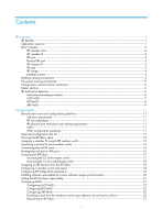
18 Configuring a member switch description 18 Configuring IRF bridge MAC persistence 19 Enabling software auto-update for system software image synchronization 20 Setting the IRF link down report delay 21 Configuring MAD 21 Configuring LACP MAD 22 Configuring BFD MAD 23 Configuring ARP - HP 6125G | HP 6125G & 6125G/XG Blade Switches IRF Configuration Guide-R2 - Page 4
an IRF fabric 28 Configuration examples 28 LACP MAD-enabled IRF configuration example 28 BFD MAD-enabled IRF configuration example 31 ARP MAD-enabled IRF configuration example 33 Support and other resources 36 Contacting HP 36 Subscription service 36 Related information 36 Documents - HP 6125G | HP 6125G & 6125G/XG Blade Switches IRF Configuration Guide-R2 - Page 5
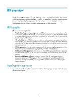
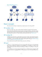
HP Intelligent Resilient Framework (IRF) technology creates a large IRF fabric from multiple switches switches. This book describes IRF concepts and guides fabric, and all the other members process services while backing up the master. When the -You can use the Ethernet link aggregation feature to - HP 6125G | HP 6125G & 6125G/XG Blade Switches IRF Configuration Guide-R2 - Page 6
port is a logical interface for the connection between IRF member devices. Every IRF-capable device supports two IRF ports. The IRF ports are named IRF-port n/1 and IRF-port n/2, where n is the member ID of the switch. The two IRF ports are referred to as "IRF-port 1" and "IRF-port 2" in this - HP 6125G | HP 6125G & 6125G/XG Blade Switches IRF Configuration Guide-R2 - Page 7
IRF links, see "General restrictions and configuration guidelines." IRF domain ID One IRF Switch A and Switch B form IRF fabric 1, and Switch C and Switch D form IRF fabric 2. The fabrics have LACP MAD detection links between them. When a member switch in one IRF fabric receives an extended LACP - HP 6125G | HP 6125G & 6125G/XG Blade Switches IRF Configuration Guide-R2 - Page 8
chassis-id/slot-number/port-index, where: • chassis-id-IRF member ID of the switch. This argument defaults to 1. • slot-number-Represents the slot number of the interface card. This argument always takes 0 on HP 6125 switches. • port-index-Port index depends on the number of ports available on the - HP 6125G | HP 6125G & 6125G/XG Blade Switches IRF Configuration Guide-R2 - Page 9
/0/1] port link-type trunk File system naming conventions On a standalone switch, you can use the name of storage device to access its file system. For more information about storage device naming conventions, see Fundamentals Configuration Guide. On an IRF fabric, you can use the name of storage - HP 6125G | HP 6125G & 6125G/XG Blade Switches IRF Configuration Guide-R2 - Page 10
config command) is enabled, saves the configuration as the startup configuration on all member switches for the next startup. • If the configuration auto-update function is disabled, saves the configuration as the startup configuration on the master for the next startup. By default, configuration - HP 6125G | HP 6125G & 6125G/XG Blade Switches IRF Configuration Guide-R2 - Page 11
these MAD mechanisms, see "Configuring MAD." Collision handling When with the mad exclude interface command. Failure recovery To merge two services from being affected. After that, recover the MAD failure. LACP MAD LACP an HP device that supports extended LACP for MAD. The IRF member switches send - HP 6125G | HP 6125G & 6125G/XG Blade Switches IRF Configuration Guide-R2 - Page 12
Figure 5 LACP MAD application VLAN interface. The MAD addresses identify the member switches and must belong to the same subnet. With BFD MAD, the master BFD session with any other member. If you execute the display bfd session command, the state of the BFD sessions is Down. • When the IRF - HP 6125G | HP 6125G & 6125G/XG Blade Switches IRF Configuration Guide-R2 - Page 13
Figure 6 BFD MAD application scenario ARP MAD ARP MAD detects multi-active collisions by using extended gratuitous ARP packets that convey the IRF domain ID and the active ID. You can set up ARP MAD links between neighbor IRF member devices, or more commonly, between each IRF member device and an - HP 6125G | HP 6125G & 6125G/XG Blade Switches IRF Configuration Guide-R2 - Page 14
Figure 7 ARP MAD application scenario Each IRF member compares the domain ID and the active ID in incoming extended gratuitous ARP packets with its domain ID and active ID: • If the domain IDs are different, the extended gratuitous ARP packet is from a different IRF fabric, and the device does not - HP 6125G | HP 6125G & 6125G/XG Blade Switches IRF Configuration Guide-R2 - Page 15
and cables, see HP 6125 Blade Switch Series Installation Guide. The SFP+ modules and SFP+ cables available for the switch are subject to change over time. For the most up-to-date list of SFP+ modules and cables, contact HP technical support or marketing staff. MAD • • • Configure at least one MAD - HP 6125G | HP 6125G & 6125G/XG Blade Switches IRF Configuration Guide-R2 - Page 16
fabric is set up, you can access the IRF fabric to manage its member switches as if they were one switch. Figure 8 Basic IRF setup flow chart HP recommends the following IRF fabric setup and configuration procedure: Task 1. Planning the IRF fabric setup 2. Assigning a member ID to each IRF member - HP 6125G | HP 6125G & 6125G/XG Blade Switches IRF Configuration Guide-R2 - Page 17
and cabling scheme For more information about hardware and cabling, see the switch installation guide. Assigning a member ID to each IRF member switch CAUTION: In an IRF fabric, changing IRF member IDs might cause undesirable configuration changes and even data loss. Before you do that, back up the - HP 6125G | HP 6125G & 6125G/XG Blade Switches IRF Configuration Guide-R2 - Page 18
view. 2. Assign an IRF member ID to the switch. Command system-view irf member member-id renumber new-member-id 3. Save the configuration. save [ safely ] [ backup | main ] [ force ] 4. Reboot the switch. reboot [ slot slot-number ] Remarks N/A The default IRF member ID is 1. Optional. If you - HP 6125G | HP 6125G & 6125G/XG Blade Switches IRF Configuration Guide-R2 - Page 19
topology without interrupting network services. To use the ring topology, you must have at least three member switches. Figure 10 Daisy the cfd, default, shutdown, description, and flow-interval commands. For more information about these commands, see Layer 2-LAN Switching Command Reference. To bind - HP 6125G | HP 6125G & 6125G/XG Blade Switches IRF Configuration Guide-R2 - Page 20
2. Enter Ethernet interface view or interface range view. Command • Enter Start the shutdown operation on the master and then the switch that has the fewest number of hops from the interface-number [ mode { enhanced | normal } ] By default, no physical port is bound to any IRF port. Make sure - HP 6125G | HP 6125G & 6125G/XG Blade Switches IRF Configuration Guide-R2 - Page 21
running configuration. save 12. Activate the IRF port configuration. irf-port-configuration switch to execute a limited set of maintenance commands. The IRF fabric supports up to 8 concurrent VTY users. The maximum number of concurrent console users equals the total number of member switches - HP 6125G | HP 6125G & 6125G/XG Blade Switches IRF Configuration Guide-R2 - Page 22
task in user view: Task Log in to a subordinate switch. Command irf switch-to member-id Remarks By default, you are placed at the master's CLI. To return to the master's CLI, use the quit command. Assigning an IRF domain ID to the IRF fabric This task is required for running LACP MAD or - HP 6125G | HP 6125G & 6125G/XG Blade Switches IRF Configuration Guide-R2 - Page 23
Step 1. Enter system view. 2. Configure the description of a member. Command Remarks system-view N/A irf member member-id description text By default, no member switch description is configured. Configuring IRF bridge MAC persistence An IRF fabric by default uses the bridge MAC address of the - HP 6125G | HP 6125G & 6125G/XG Blade Switches IRF Configuration Guide-R2 - Page 24
, you must manually update the switch with the system software image of the master. When you add a switch to the IRF switch you are adding to the IRF fabric: Step 1. Enter system view. 2. Enable the software auto-update function. Command system-view irf auto-update enable Remarks N/A By default - HP 6125G | HP 6125G & 6125G/XG Blade Switches IRF Configuration Guide-R2 - Page 25
greater the interval, the slower the service recovery. If your IRF fabric requires a fast master/subordinate or IRF link switchover or has deployed the BFD or GR feature, HP recommends setting the delay to zero seconds. Configuring MAD The switch supports the following MAD mechanisms for detecting - HP 6125G | HP 6125G & 6125G/XG Blade Switches IRF Configuration Guide-R2 - Page 26
Spanning tree feature ports. must be enabled. ARP, see Layer 3-IP Services Configuration Guide. Configuring LACP MAD When you use LACP MAD, follow these guidelines: • The intermediate device must be an HP device that support extended LACP for MAD. • If the intermediate device is in an IRF fabric - HP 6125G | HP 6125G & 6125G/XG Blade Switches IRF Configuration Guide-R2 - Page 27
Remarks The default IRF domain ID is 0. Perform this step also on the intermediate device. 4. Configure the aggregation group to operate in dynamic link-aggregation mode dynamic aggregation mode. 5. Enable LACP MAD. mad enable 6. Return to system view. quit 7. Enter Ethernet interface view - HP 6125G | HP 6125G & 6125G/XG Blade Switches IRF Configuration Guide-R2 - Page 28
Command Remarks 1. Enter system view. system-view N/A 2. Create a VLAN dedicated to BFD MAD. vlan vlan-id The default VLAN on the switch is VLAN 1. 3. Return to system view. quit N/A • Enter interface range view: 4. Enter Ethernet enable By default, BFD MAD is disabled. 9. Configure a - HP 6125G | HP 6125G & 6125G/XG Blade Switches IRF Configuration Guide-R2 - Page 29
May 5 16:15:47:733 2010 HP ARP/3/ROUTECONFLICT: Slot=5;Route conflict found To configure ARP MAD: Step 1. Enter system view. 2. Assign a domain ID to the IRF fabric. Command Ethernet interface view: interface interface-type interface-number Remarks N/A The default IRF domain ID is 0. The default - HP 6125G | HP 6125G & 6125G/XG Blade Switches IRF Configuration Guide-R2 - Page 30
to the recovery state: Step 1. Enter system view. Command system-view 2. Configure a port to not shut down when the IRF fabric mad exclude interface interface-type transits to the Recovery state. interface-number Remarks N/A By default, when an IRF fabric transits to the Recovery state - HP 6125G | HP 6125G & 6125G/XG Blade Switches IRF Configuration Guide-R2 - Page 31
Recovery-state IRF fabric, and use the reboot command to reboot all its members. After these member switches join the Active-state IRF fabric as subordinates, IRF link is recovered (see Figure 12), use the mad restore command on the Recovery-state fabric to change its state to Active for forwarding - HP 6125G | HP 6125G & 6125G/XG Blade Switches IRF Configuration Guide-R2 - Page 32
enabled IRF configuration example Network requirements Set up a two-member IRF fabric at the access layer of the enterprise network in Figure 13. Configure LACP MAD in the IRF fabric, because the IRF fabric has a multi-chassis aggregate link to Device C, an HP device that supports extended LACP. 28 - HP 6125G | HP 6125G & 6125G/XG Blade Switches IRF Configuration Guide-R2 - Page 33
formed. 1. Assign member IDs: # Keep the default member ID of Device A unchanged. # Change the member ID of Device B to 2. system-view [DeviceB] irf member 1 renumber 2 Warning: Renumbering the switch number may result in configuration change or loss. Continue? [Y/N]:y [DeviceB] 2. Power - HP 6125G | HP 6125G & 6125G/XG Blade Switches IRF Configuration Guide-R2 - Page 34
fabric. The system name of the IRF fabric is DevcieA. 4. Configure LACP MAD: # Create a dynamic aggregate interface and enable LACP MAD. Because LACP MAD is not run between IRF domains, you can use the default value 0. system-view [DeviceA] interface bridge-aggregation 2 [DeviceA-Bridge - HP 6125G | HP 6125G & 6125G/XG Blade Switches IRF Configuration Guide-R2 - Page 35
formed. 1. Assign member IDs: # Keep the default member ID of Device A unchanged. # Change the member ID of Device B to 2. system-view [DeviceB] irf member 1 renumber 2 Warning: Renumbering the switch number may result in configuration change or loss. Continue? [Y/N]:y [DeviceB] 2. Power - HP 6125G | HP 6125G & 6125G/XG Blade Switches IRF Configuration Guide-R2 - Page 36
. In this example, Device A is the master. Device B automatically reboots and joins the Device A as a subordinate switch to form an IRF fabric. The system name of the IRF fabric is DevcieA. 4. Configure BFD MAD: # Create VLAN 3, and add port GigabitEthernet 1/0/1 on Device A (member ID 1) and port - HP 6125G | HP 6125G & 6125G/XG Blade Switches IRF Configuration Guide-R2 - Page 37
formed. 1. Assign member IDs: # Keep the default member ID of Device A unchanged. # Change the member ID of Device B to 2. system-view [DeviceB] irf member 1 renumber 2 Warning: Renumbering the switch number may result in configuration change or loss. Continue? [Y/N]:y [DeviceB] 2. Power - HP 6125G | HP 6125G & 6125G/XG Blade Switches IRF Configuration Guide-R2 - Page 38
the Device A as a subordinate switch to form an IRF fabric. The system name of the IRF fabric is DevcieA. 4. Configure ARP MAD: # Enable the Because ARP MAD is not run between IRF domains, you can use the default value 0. [DeviceA] interface vlan-interface 3 [DeviceA-Vlan-interface3] ip address - HP 6125G | HP 6125G & 6125G/XG Blade Switches IRF Configuration Guide-R2 - Page 39
system-view [DeviceC] stp enable # Create VLAN 3, and add GigabitEthernet 1/0/1 and GigabitEthernet 1/0/2 to VLAN 3. [DeviceC] vlan 3 [DeviceC-vlan3] port gigabitethernet 1/0/1 gigabitethernet 1/0/2 [DeviceC-vlan3] quit 35 - HP 6125G | HP 6125G & 6125G/XG Blade Switches IRF Configuration Guide-R2 - Page 40
HP A-Series Acronyms. Websites • HP.com http://www.hp.com • HP Networking http://www.hp.com/go/networking • HP manuals http://www.hp.com/support/manuals • HP download drivers and software http://www.hp.com/support/downloads • HP software depot http://www.software.hp.com • HP Education http://www.hp - HP 6125G | HP 6125G & 6125G/XG Blade Switches IRF Configuration Guide-R2 - Page 41
Command conventions Convention Boldface Italic [ ] { x | y | ... } [ x | y | ... ] { x | y | ... } * [ x | y | ... ] * & # Description Bold text represents commands and menu items are in bold text. For example, the New User window appears; click OK. Multi-level menus are separated by angle - HP 6125G | HP 6125G & 6125G/XG Blade Switches IRF Configuration Guide-R2 - Page 42
, or firewall. Represents a routing-capable device, such as a router or Layer 3 switch. Represents a generic switch, such as a Layer 2 or Layer 3 switch, or a router that supports Layer 2 forwarding and other Layer 2 features. Port numbering in examples The port numbers in this document are for - HP 6125G | HP 6125G & 6125G/XG Blade Switches IRF Configuration Guide-R2 - Page 43
physical ports to IRF ports,15 C Configuration examples,28 Configuration synchronization mechanism,6 Configuring a member switch description,18 Configuring IRF bridge MAC persistence,19 Configuring MAD,21 Connecting physical IRF ports,14 Contacting HP,36 Conventions,37 D Displaying and maintaining
-
 1
1 -
 2
2 -
 3
3 -
 4
4 -
 5
5 -
 6
6 -
 7
7 -
8
-
9
-
10
-
11
-
12
-
13
-
14
-
15
-
16
-
17
-
18
-
19
-
20
-
21
-
22
-
23
-
24
-
25
-
26
-
27
-
28
-
29
-
30
-
31
-
32
-
33
-
34
-
35
-
36
-
37
-
38
-
39
-
40
-
41
-
42
-
43
 |
 |

HP 6125 Blade Switch Series
IRF
Configuration Guide
Part number: 5998-3154
Software version: Release 2103
Document version: 6W100-20120907