HP 6125G HP 6125G & 6125G/XG Blade Switches IRF Configuration Guide-R2 - Page 5
IRF overview, IRF benefits, Application scenario
 |
View all HP 6125G manuals
Add to My Manuals
Save this manual to your list of manuals |
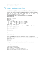
Page 5 highlights
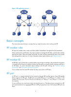
IRF overview The HP Intelligent Resilient Framework (IRF) technology creates a large IRF fabric from multiple switches to provide data center class availability and scalability. IRF virtualization technology offers processing power, interaction, unified management, and uninterrupted maintenance of multiple switches. This book describes IRF concepts and guides you through the IRF setup procedure. IRF benefits IRF delivers the following benefits: • Simplified topology and easy management-An IRF fabric appears as one node and is accessible at a single IP address on the network. You can use this IP address to log in at any member device to manage all the members of the IRF fabric. In addition, you do not need to run the spanning tree feature among the IRF members. • 1:N redundancy-In an IRF fabric, one member works as the master to manage and control the entire IRF fabric, and all the other members process services while backing up the master. When the master fails, all the other member devices elect a new master from among them to take over without interrupting services. • IRF link aggregation-You can assign several physical links between neighboring members to their IRF ports to create a load-balanced aggregate IRF connection with redundancy. • Multiple-chassis link aggregation-You can use the Ethernet link aggregation feature to aggregate the physical links between the IRF fabric and its upstream or downstream devices across the IRF members. • Network scalability and resiliency-Processing capacity of an IRF fabric equals the total processing capacities of all the members. You can increase ports, network bandwidth, and processing capacity of an IRF fabric simply by adding member devices without changing the network topology. Application scenario Figure 1 shows an IRF fabric that comprises two switches, which appear as a single node to the upper and lower layer devices. 1
-
 1
1 -
 2
2 -
 3
3 -
 4
4 -
 5
5 -
 6
6 -
 7
7 -
 8
8 -
 9
9 -
 10
10 -
 11
11 -
12
-
13
-
14
-
15
-
16
-
17
-
18
-
19
-
20
-
21
-
22
-
23
-
24
-
25
-
26
-
27
-
28
-
29
-
30
-
31
-
32
-
33
-
34
-
35
-
36
-
37
-
38
-
39
-
40
-
41
-
42
-
43
 |
 |