HP 6125G HP 6125G & 6125G/XG Blade Switches IRF Configuration Guide-R2 - Page 33
Configuration procedure, Network diagram
 |
View all HP 6125G manuals
Add to My Manuals
Save this manual to your list of manuals |
Page 33 highlights
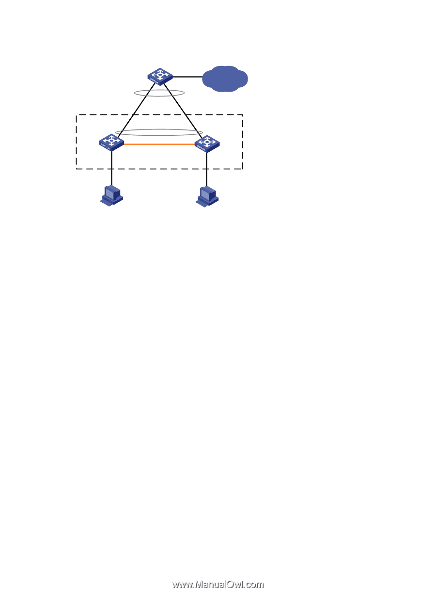
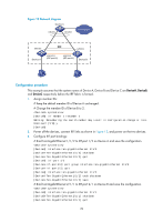
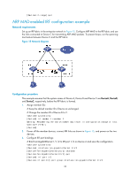
Figure 13 Network diagram Device C GE1/0/1 GE1/0/2 IP network GE1/0/2 IRF GE2/0/1 Device A XGE1/1/2 (IRF-port1/2) XGE2/1/1 (IRF-port2/1) Device B Configuration procedure This example assumes that the system names of Device A, Device B and Device C are DeviceA, DeviceB, and DeviceC respectively before the IRF fabric is formed. 1. Assign member IDs: # Keep the default member ID of Device A unchanged. # Change the member ID of Device B to 2. system-view [DeviceB] irf member 1 renumber 2 Warning: Renumbering the switch number may result in configuration change or loss. Continue? [Y/N]:y [DeviceB] 2. Power off the devices, connect IRF links as shown in Figure 13, and power on the two devices. 3. Configure IRF port bindings: # Bind Ten-GigabitEthernet 1/1/2 to IRF-port 1/2 on Device A and save the configuration. system-view [DeviceA] interface ten-gigabitethernet 1/1/2 [DeviceA-Ten-GigabitEthernet1/1/2] shutdown [DeviceA-Ten-GigabitEthernet1/1/2] quit [DeviceA] irf-port 1/2 [DeviceA-irf-port1/2] port group interface ten-gigabitethernet 1/1/2 [DeviceA-irf-port1/2] quit [DeviceA] interface ten-gigabitethernet 1/1/2 [DeviceA-Ten-GigabitEthernet1/1/2] undo shutdown [DeviceA-Ten-GigabitEthernet1/1/2] save # Bind Ten-GigabitEthernet 2/1/1 to IRF-port 2/1 on Device B and save the configuration. system-view [DeviceB] interface ten-gigabitethernet 2/1/1 [DeviceB-Ten-GigabitEthernet2/1/1] shutdown [DeviceB-Ten-GigabitEthernet2/1/1] quit 29
-
 1
1 -
2
-
3
-
4
-
5
-
6
-
7
-
8
-
9
-
10
-
11
-
12
-
13
-
14
-
15
-
16
-
17
-
18
-
19
-
20
-
21
-
22
-
23
-
24
-
25
-
26
-
27
-
 28
28 -
 29
29 -
 30
30 -
 31
31 -
 32
32 -
 33
33 -
 34
34 -
 35
35 -
 36
36 -
 37
37 -
 38
38 -
39
-
40
-
41
-
42
-
43
 |
 |