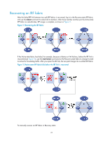
HP 6125G HP 6125G & 6125G/XG Blade Switches IRF Configuration Guide-R2 - Page 36
GigabitEthernet 2/0/1 on Device B member ID 2 to VLAN 3., Activate IRF port configuration on Device B.
 |
View all HP 6125G manuals
Add to My Manuals
Save this manual to your list of manuals |
Page 36 highlights
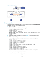
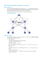
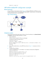
[DeviceA] interface ten-gigabitethernet 1/1/2 [DeviceA-Ten-GigabitEthernet1/1/2] shutdown [DeviceA-Ten-GigabitEthernet1/1/2] quit [DeviceA] irf-port 1/2 [DeviceA-irf-port1/2] port group interface ten-gigabitethernet 1/1/2 [DeviceA-irf-port1/2] quit [DeviceA] interface ten-gigabitethernet 1/1/2 [DeviceA-Ten-GigabitEthernet1/1/2] undo shutdown [DeviceA-Ten-GigabitEthernet1/1/2] save # Bind Ten-GigabitEthernet 2/1/1 to IRF-port 2/1 and save the configuration. system-view [DeviceB] interface ten-gigabitethernet 2/1/1 [DeviceB-Ten-GigabitEthernet2/1/1] shutdown [DeviceB-Ten-GigabitEthernet2/1/1] quit [DeviceB] irf-port 2/1 [DeviceB-irf-port2/1] port group interface ten-gigabitethernet 2/1/1 [DeviceB-irf-port2/1] quit [DeviceB] interface ten-gigabitethernet 2/1/1 [DeviceB-Ten-GigabitEthernet2/1/1] undo shutdown [DeviceB-Ten-GigabitEthernet2/1/1] save # Activate IRF port configuration on Device A. [DeviceA-Ten-GigabitEthernet1/1/2] quit [DeviceA] irf-port-configuration active # Activate IRF port configuration on Device B. [DeviceB-Ten-GigabitEthernet2/1/1] quit [DeviceB] irf-port-configuration active After the IRF port configuration is activated, the two devices automatically elect a master. In this example, Device A is the master. Device B automatically reboots and joins the Device A as a subordinate switch to form an IRF fabric. The system name of the IRF fabric is DevcieA. 4. Configure BFD MAD: # Create VLAN 3, and add port GigabitEthernet 1/0/1 on Device A (member ID 1) and port GigabitEthernet 2/0/1 on Device B (member ID 2) to VLAN 3. system-view [DeviceA] vlan 3 [DeviceA-vlan3] port gigabitethernet 1/0/1 gigabitethernet 2/0/1 [DeviceA-vlan3] quit # Create VLAN-interface 3 and configure a MAD IP address for each member device on the interface. [DeviceA] interface vlan-interface 3 [DeviceA-Vlan-interface3] mad bfd enable [DeviceA-Vlan-interface3] mad ip address 192.168.2.1 24 member 1 [DeviceA-Vlan-interface3] mad ip address 192.168.2.2 24 member 2 [DeviceA-Vlan-interface3] quit # Connect the BFD MAD links as shown in Figure 14. # Disable the spanning tree feature on GigabitEthernet 1/0/1 and GigabitEthernet 2/0/1. [DeviceA] interface range gigabitethernet 1/0/1 gigabitethernet 2/0/1 [DeviceA-if-range] undo stp enable 32
-
 1
1 -
2
-
3
-
4
-
5
-
6
-
7
-
8
-
9
-
10
-
11
-
12
-
13
-
14
-
15
-
16
-
17
-
18
-
19
-
20
-
21
-
22
-
23
-
24
-
25
-
26
-
27
-
28
-
29
-
30
-
 31
31 -
 32
32 -
 33
33 -
 34
34 -
 35
35 -
 36
36 -
 37
37 -
 38
38 -
 39
39 -
 40
40 -
 41
41 -
42
-
43
 |
 |