HP 6125G HP 6125G & 6125G/XG Blade Switches IRF Configuration Guide-R2 - Page 35
BFD MAD-enabled IRF configuration example, Network requirements, Configuration procedure
 |
View all HP 6125G manuals
Add to My Manuals
Save this manual to your list of manuals |
Page 35 highlights
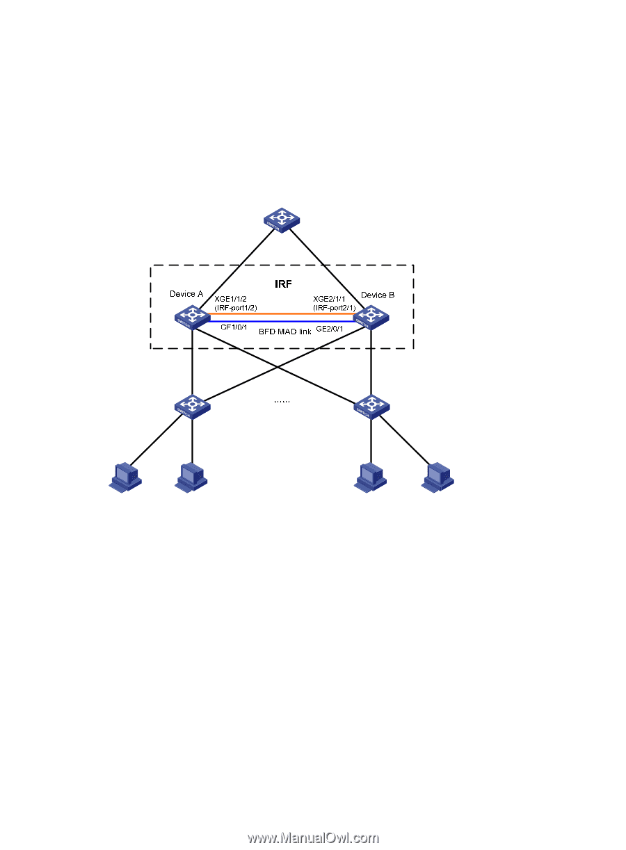
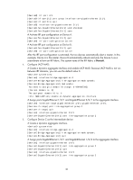
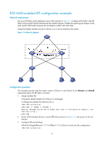
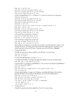
BFD MAD-enabled IRF configuration example Network requirements Set up an IRF fabric at the distribution layer of the network in Figure 14. Configure BFD MAD in the IRF fabric and set up BFD MAD links between the member devices. Disable the spanning tree feature on the ports used for BFD MAD, because the two features conflict with each other. Assign the highest member priority to Device A so it can be elected as the master. Figure 14 Network diagram Configuration procedure This example assumes that the system names of Device A and Device B are DeviceA and DeviceB respectively before the IRF fabric is formed. 1. Assign member IDs: # Keep the default member ID of Device A unchanged. # Change the member ID of Device B to 2. system-view [DeviceB] irf member 1 renumber 2 Warning: Renumbering the switch number may result in configuration change or loss. Continue? [Y/N]:y [DeviceB] 2. Power off the member devices, connect IRF links as shown in Figure 14, and power on the two devices. 3. Configure IRF port bindings: # Bind Ten-GigabitEthernet 1/1/2 to IRF-port 1/2 on Device A and save the configuration. system-view 31
-
 1
1 -
2
-
3
-
4
-
5
-
6
-
7
-
8
-
9
-
10
-
11
-
12
-
13
-
14
-
15
-
16
-
17
-
18
-
19
-
20
-
21
-
22
-
23
-
24
-
25
-
26
-
27
-
28
-
29
-
 30
30 -
 31
31 -
 32
32 -
 33
33 -
 34
34 -
 35
35 -
 36
36 -
 37
37 -
 38
38 -
 39
39 -
 40
40 -
41
-
42
-
43
 |
 |