HP 6125G HP 6125G & 6125G/XG Blade Switches IRF Configuration Guide-R2 - Page 16
Setup and configuration task list
 |
View all HP 6125G manuals
Add to My Manuals
Save this manual to your list of manuals |
Page 16 highlights
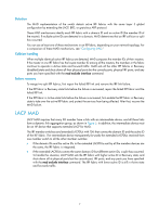
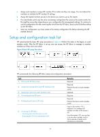
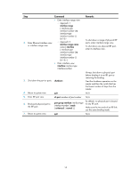
• Assign each member a unique IRF member ID to make sure they can merge. You must reboot the members to validate the IRF member ID settings. • Assign the highest member priority to the device you want to use as the master. • If a subordinate switch uses the same next-startup configuration file name as the master switch, the file might be overwritten depending on your configuration file management settings. To continue to use the configuration file after removing the switch from the IRF fabric, back up the file before setting up the IRF fabric. • Save any configuration you have made to the startup configuration file before rebooting the IRF member devices. Setup and configuration task list HP recommends the basic IRF setup procedure in Figure 8. Perform the tasks in this figure on each member switch. After the IRF fabric is set up, you can access the IRF fabric to manage its member switches as if they were one switch. Figure 8 Basic IRF setup flow chart HP recommends the following IRF fabric setup and configuration procedure: Task 1. Planning the IRF fabric setup 2. Assigning a member ID to each IRF member switch 3. Specifying a priority for each member switch 4. Connecting physical IRF ports 5. Binding physical ports to IRF ports 6. Accessing the IRF fabric: { Accessing the CLI of the master switch { Accessing the CLI of a subordinate switch Remarks Required. Required. Perform this task on each member switch. Optional. Required. Required. Perform this task on each member switch. Login to the master's CLI is required. You configure all member switches at the master's CLI. From the master's CLI, you can log in to any other member switch's CLI to execute a limited set of maintenance commands. 12
-
 1
1 -
2
-
3
-
4
-
5
-
6
-
7
-
8
-
9
-
10
-
 11
11 -
 12
12 -
 13
13 -
 14
14 -
 15
15 -
 16
16 -
 17
17 -
 18
18 -
 19
19 -
 20
20 -
 21
21 -
22
-
23
-
24
-
25
-
26
-
27
-
28
-
29
-
30
-
31
-
32
-
33
-
34
-
35
-
36
-
37
-
38
-
39
-
40
-
41
-
42
-
43
 |
 |
