HP 6125G HP 6125G & 6125G/XG Blade Switches IRF Configuration Guide-R2 - Page 8
IRF merge, Member priority, Interface naming conventions
 |
View all HP 6125G manuals
Add to My Manuals
Save this manual to your list of manuals |
Page 8 highlights
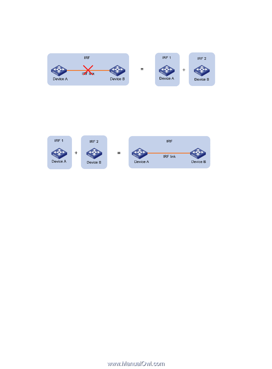
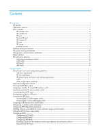
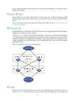
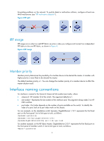
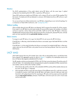
forwarding problems on the network. To quickly detect a multi-active collision, configure at least one MAD mechanisms (see "IRF multi-active detection"). Figure 3 IRF split IRF merge IRF merge occurs when two split IRF fabrics re-unite or when you configure and connect two independent IRF fabrics to be one IRF fabric, as shown in Figure 4. Figure 4 IRF merge Member priority Member priority determines the possibility of a member device to be elected the master. A member with higher priority is more likely to be elected the master. The default member priority is 1. You can change the member priority of a member device to affect the master election result. Interface naming conventions An interface is named in the format of chassis-id/slot-number/port-index, where: • chassis-id-IRF member ID of the switch. This argument defaults to 1. • slot-number-Represents the slot number of the interface card. This argument always takes 0 on HP 6125 switches. • port-index-Port index depends on the number of ports available on the switch. To identify the index of a port, look at its port index mark on the chassis. For one example, on the standalone switch Sysname, GigabitEthernet 1/0/1 represents the first fixed port on the front panel. Set its link type to trunk, as follows: system-view [Sysname] interface gigabitethernet 1/0/1 [Sysname-GigabitEthernet1/0/1] port link-type trunk For another example, on the IRF fabric Master, GigabitEthernet 3/0/1 represents the first fixed port on the front panel of member switch 3. Set its link type to trunk, as follows: system-view 4
-
 1
1 -
2
-
 3
3 -
 4
4 -
 5
5 -
 6
6 -
 7
7 -
 8
8 -
 9
9 -
 10
10 -
 11
11 -
 12
12 -
 13
13 -
14
-
15
-
16
-
17
-
18
-
19
-
20
-
21
-
22
-
23
-
24
-
25
-
26
-
27
-
28
-
29
-
30
-
31
-
32
-
33
-
34
-
35
-
36
-
37
-
38
-
39
-
40
-
41
-
42
-
43
 |
 |