HP 6125G HP 6125G & 6125G/XG Blade Switches IRF Configuration Guide-R2 - Page 19
Binding physical ports to IRF ports
 |
View all HP 6125G manuals
Add to My Manuals
Save this manual to your list of manuals |
Page 19 highlights
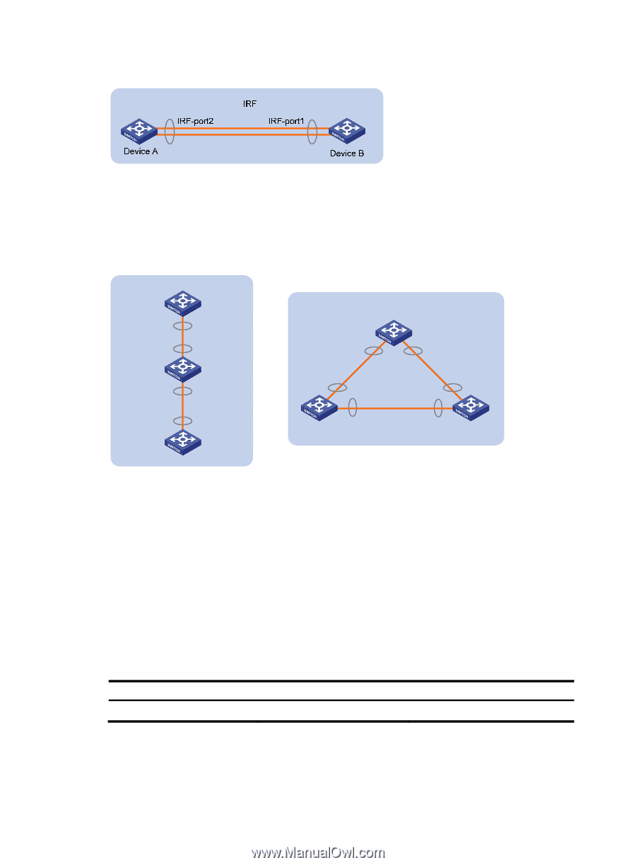
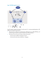
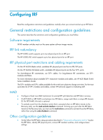
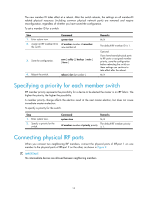
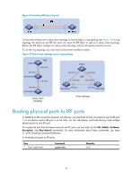
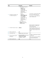
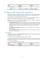
Figure 9 Connecting IRF physical ports Connect the switches into a daisy chain topology or more reliably, a ring topology (see Figure 10). In ring topology, the failure of one IRF link does not cause the IRF fabric to split as in daisy chain topology. Rather, the IRF fabric changes to a daisy chain topology without interrupting network services. To use the ring topology, you must have at least three member switches. Figure 10 Daisy chain topology versus ring topology Master IRF-Port1 Subordinate IRF IRF-Port2 IRF-Port2 Master IRF-Port1 IRF-Port2 IRF IRF-Port2 IRF-Port1 IRF-Port1 Subordinate Daisy chain topology Subordinate IRF-Port1 IRF-Port2 Subordinate Ring topology Binding physical ports to IRF ports To establish an IRF connection between two devices, you must bind at least one physical port to IRF-port 1 on one device and to IRF-port 2 on the other. For link redundancy and load sharing, bind multiple physical ports to one IRF port. On a physical port that has been bound to an IRF port, you can only use the cfd, default, shutdown, description, and flow-interval commands. For more information about these commands, see Layer 2-LAN Switching Command Reference. To bind physical ports to IRF ports: Step 1. Enter system view. Command system-view Remarks N/A 15
-
 1
1 -
2
-
3
-
4
-
5
-
6
-
7
-
8
-
9
-
10
-
11
-
12
-
13
-
 14
14 -
 15
15 -
 16
16 -
 17
17 -
 18
18 -
 19
19 -
 20
20 -
 21
21 -
 22
22 -
 23
23 -
 24
24 -
25
-
26
-
27
-
28
-
29
-
30
-
31
-
32
-
33
-
34
-
35
-
36
-
37
-
38
-
39
-
40
-
41
-
42
-
43
 |
 |