HP 6125G HP 6125G & 6125G/XG Blade Switches IRF Configuration Guide-R2 - Page 37
ARP MAD-enabled IRF configuration example, Network requirements, Configuration procedure
 |
View all HP 6125G manuals
Add to My Manuals
Save this manual to your list of manuals |
Page 37 highlights
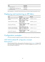
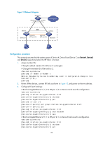
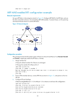
[DeviceA-if-range] quit ARP MAD-enabled IRF configuration example Network requirements Set up an IRF fabric in the enterprise network in Figure 15. Configure ARP MAD in the IRF fabric and use the links connected to Device C for transmitting ARP MAD packets. To prevent loops, run the spanning tree feature between Device C and the IRF fabric. Figure 15 Network diagram Configuration procedure This example assumes that the system names of Device A, Device B and Device C are DeviceA, DeviceB, and DeviceC, respectively, before the IRF fabric is formed. 1. Assign member IDs: # Keep the default member ID of Device A unchanged. # Change the member ID of Device B to 2. system-view [DeviceB] irf member 1 renumber 2 Warning: Renumbering the switch number may result in configuration change or loss. Continue? [Y/N]:y [DeviceB] 2. Power off the member devices, connect IRF links as shown in Figure 15, and power on the two devices. 3. Configure IRF port bindings: # Bind Ten-GigabitEthernet 1/1/2 to IRF-port 1/2 on Device A and save the configuration. system-view [DeviceA] interface ten-gigabitethernet 1/1/2 [DeviceA-Ten-GigabitEthernet1/1/2] shutdown [DeviceA-Ten-GigabitEthernet1/1/2] quit [DeviceA] irf-port 1/2 [DeviceA-irf-port1/2] port group interface ten-gigabitethernet 1/1/2 33
-
 1
1 -
2
-
3
-
4
-
5
-
6
-
7
-
8
-
9
-
10
-
11
-
12
-
13
-
14
-
15
-
16
-
17
-
18
-
19
-
20
-
21
-
22
-
23
-
24
-
25
-
26
-
27
-
28
-
29
-
30
-
31
-
 32
32 -
 33
33 -
 34
34 -
 35
35 -
 36
36 -
 37
37 -
 38
38 -
 39
39 -
 40
40 -
 41
41 -
 42
42 -
43
 |
 |
