HP 6125G HP 6125G & 6125G/XG Blade Switches IRF Configuration Guide-R2 - Page 6
Basic concepts, IRF member roles, IRF member ID, IRF port
 |
View all HP 6125G manuals
Add to My Manuals
Save this manual to your list of manuals |
Page 6 highlights
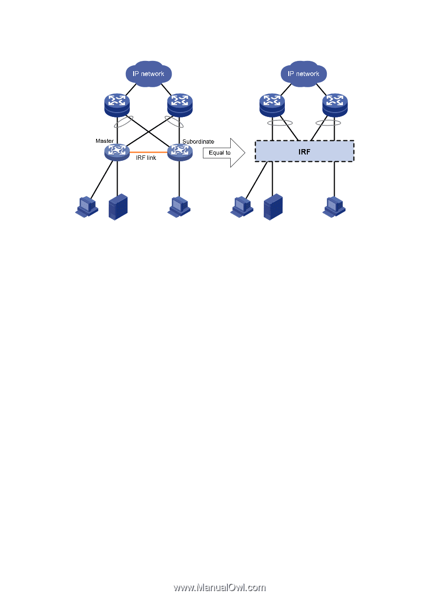
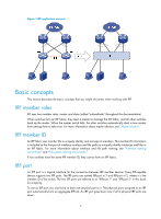
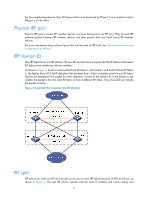
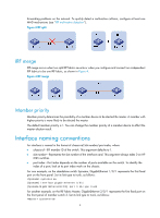
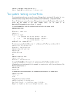
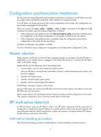
Figure 1 IRF application scenario Basic concepts This section describes the basic concepts that you might encounter when working with IRF. IRF member roles IRF uses two member roles: master and slave (called "subordinate" throughout the documentation). When switches form an IRF fabric, they elect a master to manage the IRF fabric, and all other switches back up the master. When the master switch fails, the other switches automatically elect a new master from among them to take over. For more information about master election, see "Master election." IRF member ID An IRF fabric uses member IDs to uniquely identify and manage its members. This member ID information is included as the first part of interface numbers and file paths to uniquely identify interfaces and files in an IRF fabric. For more information about interface and file path naming, see "Interface naming conventions" and "File system naming conventions." If two switches have the same IRF member ID, they cannot form an IRF fabric. IRF port An IRF port is a logical interface for the connection between IRF member devices. Every IRF-capable device supports two IRF ports. The IRF ports are named IRF-port n/1 and IRF-port n/2, where n is the member ID of the switch. The two IRF ports are referred to as "IRF-port 1" and "IRF-port 2" in this book for simplicity. To use an IRF port, you must bind at least one physical port to it. The physical ports assigned to an IRF port automatically form an aggregate IRF link. An IRF port goes down only if all its physical IRF ports are down. 2
-
 1
1 -
 2
2 -
 3
3 -
 4
4 -
 5
5 -
 6
6 -
 7
7 -
 8
8 -
 9
9 -
 10
10 -
 11
11 -
 12
12 -
13
-
14
-
15
-
16
-
17
-
18
-
19
-
20
-
21
-
22
-
23
-
24
-
25
-
26
-
27
-
28
-
29
-
30
-
31
-
32
-
33
-
34
-
35
-
36
-
37
-
38
-
39
-
40
-
41
-
42
-
43
 |
 |