HP Dc5000 HP Compaq Business Desktop dc5000 Series Service Reference Guide 2nd - Page 130
ATA/ATAPI IDE Standard Drive Cable, Pin Power, Pin Power for CPU, Reset, Ground, INTRQ, IOCS16, DMARQ
 |
UPC - 829160313740
View all HP Dc5000 manuals
Add to My Manuals
Save this manual to your list of manuals |
Page 130 highlights
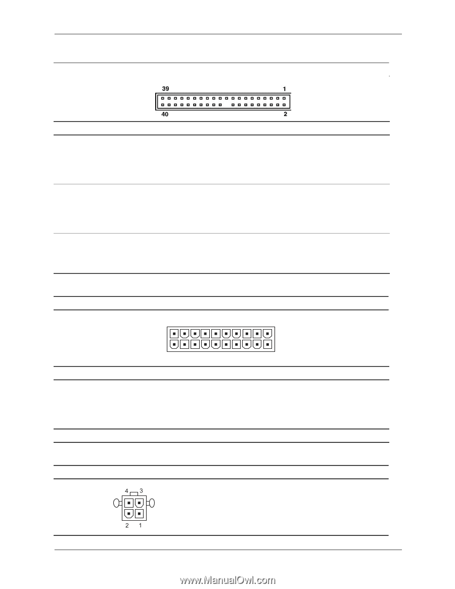
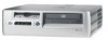
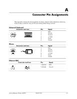
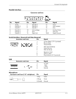
Connector Pin Assignments ATA/ATAPI (IDE) Standard Drive Cable Connector Pin Signal 1 Reset 2 Ground 3 DD7 4 DD8 5 DD6 6 DD9 7 DD5 8 DD10 9 DD4 10 DD11 11 DD3 12 DD12 13 DD2 14 DD13 20-Pin Power Pin Signal 15 DD1 16 DD14 17 DD0 18 DD15 19 Ground 20 (Key) 21 DMARQ 22 Ground 23 DIOW 24 Ground 25 DIOR 26 Ground 27 IORDY 28 CSEL Pin Signal 29 DMAK 30 Ground 31 INTRQ 32 IOCS16 33 DA1 34 PDIAG (cable detect) 35 DA0 36 DA2 37 CS1FX 38 CS3FX 39 DASP 40 Ground Connector 20 11 10 1 Pin Signal Pin Signal 1 +3.3 V 2 +3.3 V 3 GND 4 +5 V 5 GND 6 +5 V 7 GND 8 POK 9 +5 Vaux 10 +12 V *Open for d300 series computers; -5V for all others Pin Signal 11 +3.3 V 12 -12 V 13 GND 14 PSON 15 GND 4-Pin Power (for CPU) Connector and Icon Pin Signal 1 GND 2 GND 3 +12 V 4 -12 V Pin Signal 16 GND 17 GND 18 open* 19 +5 V 20 +5 V A-6 360201-002 Service Reference Guide, dc5000
-
 1
1 -
2
-
3
-
4
-
5
-
6
-
7
-
8
-
9
-
10
-
11
-
12
-
13
-
14
-
15
-
16
-
17
-
18
-
19
-
20
-
21
-
22
-
23
-
24
-
25
-
26
-
27
-
28
-
29
-
30
-
31
-
32
-
33
-
34
-
35
-
36
-
37
-
38
-
39
-
40
-
41
-
42
-
43
-
44
-
45
-
46
-
47
-
48
-
49
-
50
-
51
-
52
-
53
-
54
-
55
-
56
-
57
-
58
-
59
-
60
-
61
-
62
-
63
-
64
-
65
-
66
-
67
-
68
-
69
-
70
-
71
-
72
-
73
-
74
-
75
-
76
-
77
-
78
-
79
-
80
-
81
-
82
-
83
-
84
-
85
-
86
-
87
-
88
-
89
-
90
-
91
-
92
-
93
-
94
-
95
-
96
-
97
-
98
-
99
-
100
-
101
-
102
-
103
-
104
-
105
-
106
-
107
-
108
-
109
-
110
-
111
-
112
-
113
-
114
-
115
-
116
-
117
-
118
-
119
-
120
-
121
-
122
-
123
-
124
-
 125
125 -
 126
126 -
 127
127 -
 128
128 -
 129
129 -
 130
130 -
 131
131 -
 132
132 -
 133
133 -
 134
134 -
 135
135 -
136
-
137
-
138
-
139
-
140
-
141
-
142
-
143
-
144
-
145
-
146
-
147
-
148
-
149
-
150
-
151
-
152
-
153
-
154
-
155
-
156
-
157
-
158
-
159
-
160
-
161
-
162
-
163
-
164
-
165
-
166
-
167
-
168
-
169
-
170
-
171
-
172
-
173
-
174
-
175
-
176
-
177
-
178
-
179
-
180
 |
 |