HP Dc5000 HP Compaq Business Desktop dc5000 Series Service Reference Guide 2nd - Page 88
System Board, Preparation for Disassembly, Access Panel, PCI Expansion Card
 |
UPC - 829160313740
View all HP Dc5000 manuals
Add to My Manuals
Save this manual to your list of manuals |
Page 88 highlights
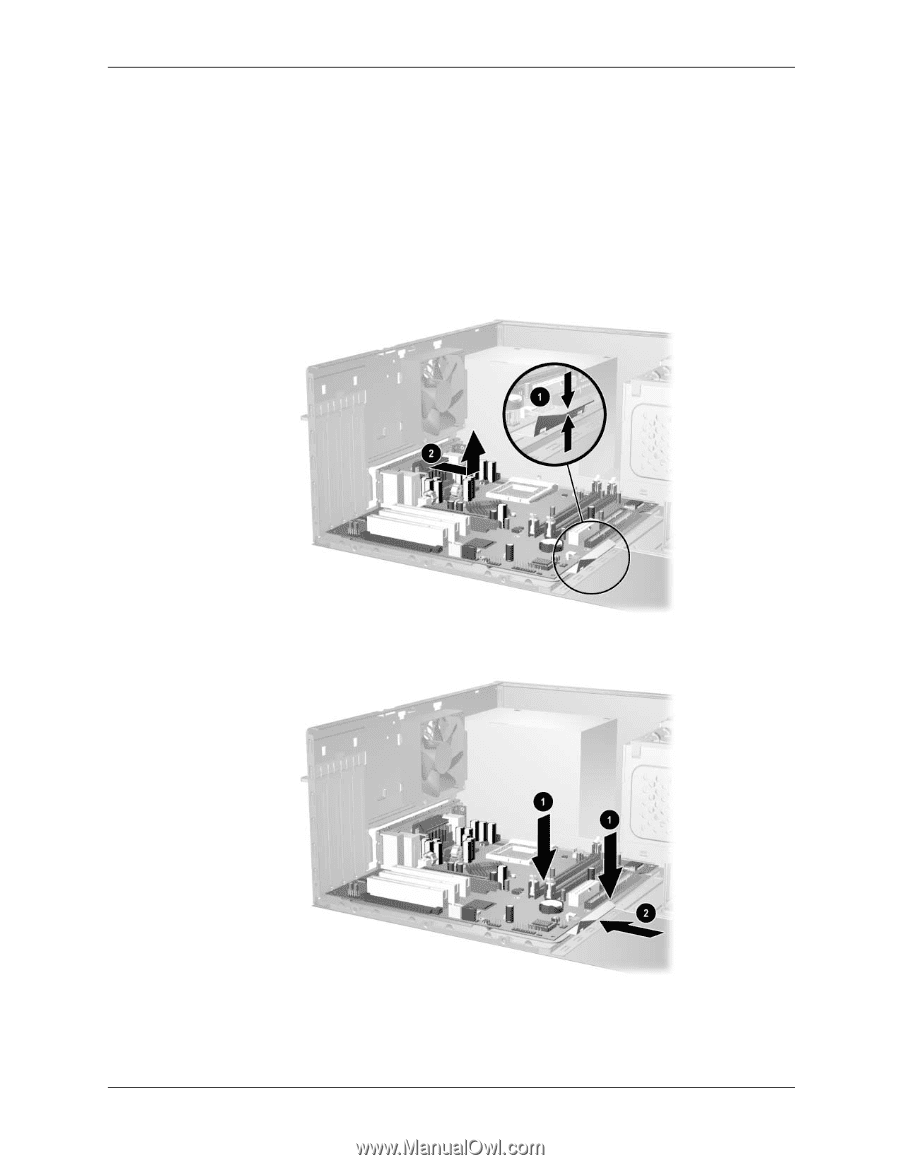
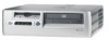
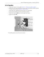
Removal and Replacement Procedures- Microtower (µT) Chassis 6.14 System Board 1. Prepare the computer for disassembly (Section 6.1, "Preparation for Disassembly"). 2. Remove the access panel and rotate the computer so the system board is parallel to the table to make it easier to work on (Section 6.3, "Access Panel"). 3. Remove all PCI expansion boards (Section 6.7.2, "PCI Expansion Card"). 4. Disconnect all cables connected to the system board, noting their location for reinstallation. 5. Compress the system board tray handle 1 to release the latch and slide the system board tray towards the front of the computer 2 to free it from the back of the chassis. To install the system board, slide the tray assembly into the chassis and press down on the two places shown in the drawing 1 while sliding the tray into its locked position 2. 6-26 360201-002 Service Reference Guide, dc5000
-
 1
1 -
2
-
3
-
4
-
5
-
6
-
7
-
8
-
9
-
10
-
11
-
12
-
13
-
14
-
15
-
16
-
17
-
18
-
19
-
20
-
21
-
22
-
23
-
24
-
25
-
26
-
27
-
28
-
29
-
30
-
31
-
32
-
33
-
34
-
35
-
36
-
37
-
38
-
39
-
40
-
41
-
42
-
43
-
44
-
45
-
46
-
47
-
48
-
49
-
50
-
51
-
52
-
53
-
54
-
55
-
56
-
57
-
58
-
59
-
60
-
61
-
62
-
63
-
64
-
65
-
66
-
67
-
68
-
69
-
70
-
71
-
72
-
73
-
74
-
75
-
76
-
77
-
78
-
79
-
80
-
81
-
82
-
 83
83 -
 84
84 -
 85
85 -
 86
86 -
 87
87 -
 88
88 -
 89
89 -
 90
90 -
 91
91 -
 92
92 -
 93
93 -
94
-
95
-
96
-
97
-
98
-
99
-
100
-
101
-
102
-
103
-
104
-
105
-
106
-
107
-
108
-
109
-
110
-
111
-
112
-
113
-
114
-
115
-
116
-
117
-
118
-
119
-
120
-
121
-
122
-
123
-
124
-
125
-
126
-
127
-
128
-
129
-
130
-
131
-
132
-
133
-
134
-
135
-
136
-
137
-
138
-
139
-
140
-
141
-
142
-
143
-
144
-
145
-
146
-
147
-
148
-
149
-
150
-
151
-
152
-
153
-
154
-
155
-
156
-
157
-
158
-
159
-
160
-
161
-
162
-
163
-
164
-
165
-
166
-
167
-
168
-
169
-
170
-
171
-
172
-
173
-
174
-
175
-
176
-
177
-
178
-
179
-
180
 |
 |