HP Dc5000 HP Compaq Business Desktop dc5000 Series Service Reference Guide 2nd - Page 47
Ultra ATA Drive Guidelines and Features, 4.1 Ultra ATA Jumpers, 4.2.1 Cable Layout
 |
UPC - 829160313740
View all HP Dc5000 manuals
Add to My Manuals
Save this manual to your list of manuals |
Page 47 highlights
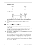
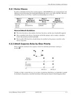
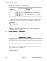
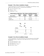
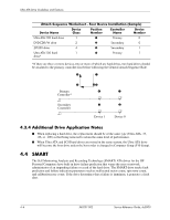
4 Ultra ATA Drive Guidelines and Features 4.1 Ultra ATA Jumpers Ultra ATA drives are configured by means of jumper settings. Factory-installed drives ship with the jumpers preset to the cable-select mode; therefore, no jumper setting changes are required on factory pre installed, replacement, or option drives. With cable-select, the drive is configured as either Master (Drive/Device 0) or Slave (Drive/Device 1) by its physical attachment to the cable. If you purchase a third-party hard drive, refer to the documentation included with the drive kit to ensure proper cable installation and configuration. ✎ All drives on a controller channel need to have their jumpers either in the cable-select mode or have the individual drive jumper installed on the appropriate Master (Drive/Device 0) or Slave (Drive/Device 1) position. 4.2 Ultra ATA Cables When installing a second device on either the primary or secondary controller, you must use an industry standard 80-conductor Ultra ATA cable for optimal performance. These cables have a maximum length of 18 inches and a maximum distance of 6 inches between the two devices for a two-drive cable. Drives operating at speeds faster than those of the Ultra ATA-33 devices require industry-standard 40-pin, 80-conductor cables to maintain the higher data transfer rates possible with the improved technology. When using Ultra ATA-133, -100, -66, and slower -33 drives in the same system, each drive will operate at its appropriate data transfer rate. 4.2.1 Cable Layout The faces of industry-standard cable connectors are color coded for easy recognition: ■ System board connector = blue face ■ Device 0 connector = black face ■ Device 1 connector = gray face ✎ The color code of an industry-standard cable is valid only if the drive's jumper is in the cable-select position. Service Reference Guide, dc5000 360201-002 4-1
-
 1
1 -
2
-
3
-
4
-
5
-
6
-
7
-
8
-
9
-
10
-
11
-
12
-
13
-
14
-
15
-
16
-
17
-
18
-
19
-
20
-
21
-
22
-
23
-
24
-
25
-
26
-
27
-
28
-
29
-
30
-
31
-
32
-
33
-
34
-
35
-
36
-
37
-
38
-
39
-
40
-
41
-
 42
42 -
 43
43 -
 44
44 -
 45
45 -
 46
46 -
 47
47 -
 48
48 -
 49
49 -
 50
50 -
 51
51 -
 52
52 -
53
-
54
-
55
-
56
-
57
-
58
-
59
-
60
-
61
-
62
-
63
-
64
-
65
-
66
-
67
-
68
-
69
-
70
-
71
-
72
-
73
-
74
-
75
-
76
-
77
-
78
-
79
-
80
-
81
-
82
-
83
-
84
-
85
-
86
-
87
-
88
-
89
-
90
-
91
-
92
-
93
-
94
-
95
-
96
-
97
-
98
-
99
-
100
-
101
-
102
-
103
-
104
-
105
-
106
-
107
-
108
-
109
-
110
-
111
-
112
-
113
-
114
-
115
-
116
-
117
-
118
-
119
-
120
-
121
-
122
-
123
-
124
-
125
-
126
-
127
-
128
-
129
-
130
-
131
-
132
-
133
-
134
-
135
-
136
-
137
-
138
-
139
-
140
-
141
-
142
-
143
-
144
-
145
-
146
-
147
-
148
-
149
-
150
-
151
-
152
-
153
-
154
-
155
-
156
-
157
-
158
-
159
-
160
-
161
-
162
-
163
-
164
-
165
-
166
-
167
-
168
-
169
-
170
-
171
-
172
-
173
-
174
-
175
-
176
-
177
-
178
-
179
-
180
 |
 |